
Explosion-proof capacitor

A capacitor and negative electrode technology, applied in the field of explosion-proof capacitors, can solve problems such as potential safety hazards, shorten the service life of capacitors, and explosion, and achieve the effects of solving solder joints that are easily affected by temperature, improving electrical performance, and increasing service life.

Inactive Publication Date: 2016-04-13
SUZHOU QUANSU SHIP ELECTRONICS CO LTD
View PDF6 Cites 0 Cited by
  • Summary
  • Abstract
  • Description
  • Claims
  • Application Information

AI Technical Summary

Problems solved by technology

There is a cover plate installed between the capacitor body and the external environment, which is used to seal the inside of the capacitor to prevent contact with the external environment, and is also used to install and disassemble the capacitor. There will be a gap between the plate and the shell. The sealing method of the capacitor in the prior art is mainly welding, and then adding sealing material to the welding point and the cover plate to enhance the sealing performance. However, the temperature of the welding point is very obvious, so it will As a result, the sealing of the capacitor is reduced, causing safety accidents such as electric leakage, and due to the thermal expansion and contraction inside the capacitor, it will cause the shell to deform or even explode, posing a safety hazard, and it will also cause damage to the exposed lead wires, resulting in a change in the stability of the capacitor. low, reducing the service life of the capacitor

Method used


Image

  • Explosion-proof capacitor
  • Explosion-proof capacitor
  • Explosion-proof capacitor

Examples


Embodiment Construction

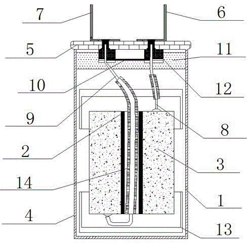
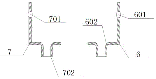
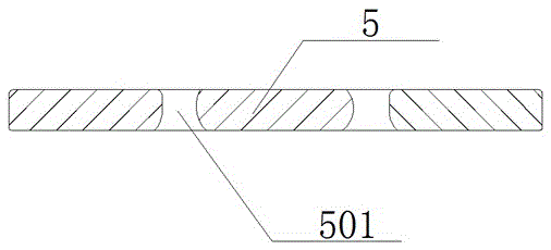
[0020] like Figure 1 to Figure 4 The shown explosion-proof capacitor includes a shell 1, an explosion-proof end cover 5, a positive electrode pin 6 and a negative electrode pin 7, the shell 1 is wrapped with a layer of plastic film 4, and two A vertical mandrel 2 and a polypropylene film layer 3, the polypropylene film layer 3 is wound on the outside of the corresponding mandrel 2, an explosion-proof end cover 5 is sealed and installed on the top of the housing 1, and the explosion-proof end cover 5 is symmetrically arranged Two mounting holes 501, the positive electrode pin 6 and the negative electrode pin 7 pass through the two mounting holes 501 on the explosion-proof end cover 5 and are respectively connected to the positive electrode wiring 8 and the negative electrode wiring 9, and the positive electrode wiring 8 is connected to The top end of the polypropylene film layer 3, the negative electrode connection 9 is connected to the bottom end of the polypropylene film lay...


PUM


Abstract

The invention discloses an explosion-proof capacitor, which comprises a shell, an explosion-proof end cover, a positive electrode pin and a negative electrode pin, wherein two vertical core rods and polypropylene film layers are arranged in the shell; each polypropylene film layer is wound outside the corresponding core rod; two mounting holes are symmetrically formed in the explosion-proof end cover; and the positive electrode pin and the negative electrode pin pass through the two mounting holes in the explosion-proof end cover and are connected with a positive electrode wiring and a negative electrode wiring respectively. The explosion-proof capacitor is simple in structure and multi-sealed; the problem that a solder joint is easily affected by the temperature in a traditional welding sealing technology is solved; mounting and stamping of elements are facilitated by a connecting hole with a waist-shaped structure; loss of the capacitor in the operating process is reduced through an arranged insulating sleeve; various electrical properties of the capacitor are improved; the service lifetime of the capacitor is prolonged; and the capacitor can be safe, explosion-proof and safe to use through arranged explosion-proof end cover and explosion-proof plate.

Description

technical field [0001] The invention relates to the field of electrical facilities, in particular to an explosion-proof capacitor. Background technique [0002] At present, the existing capacitors are usually referred to simply as capacitors, which are "charged containers" and are devices that hold charges. Capacitors are one of the most widely used electronic components in electronic equipment, and are widely used in DC blocking, coupling, bypass, filtering, tuning loops, energy conversion, control, etc. in circuits. There is a cover plate installed between the capacitor body and the external environment, which is used to seal the inside of the capacitor to prevent contact with the external environment, and is also used to install and disassemble the capacitor. There will be a gap between the plate and the shell. The sealing method of the capacitor in the prior art is mainly welding, and then adding sealing material to the welding point and the cover plate to enhance the s...

Claims


Application Information

Patent Timeline
IPC IPC(8): H01G2/10H01G2/14
CPCH01G2/14H01G2/10H01G2/103
Inventor 权高清
Owner SUZHOU QUANSU SHIP ELECTRONICS CO LTD
Learn More