
Compact circular waveguide TM01-TE01 mode converter

A mode converter and circular waveguide technology, applied in waveguide devices, electrical components, circuits, etc., can solve the problems of input and output not on the same axis, large size, complex structure, etc., and achieve suppression of asymmetrical modes, light weight, The effect of shortening the spatial distance

Active Publication Date: 2016-04-13
XIAN INSTITUE OF SPACE RADIO TECH
View PDF1 Cites 4 Cited by
  • Summary
  • Abstract
  • Description
  • Claims
  • Application Information

AI Technical Summary

Problems solved by technology

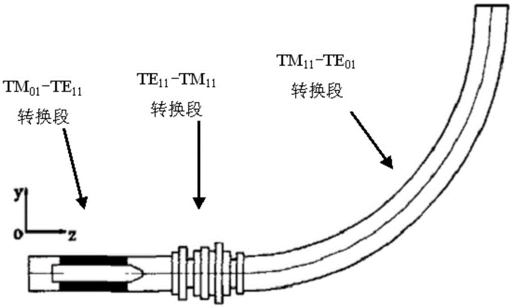
Although this conversion structure can effectively convert the circular waveguide TM01 mode into the TE01 mode, the structure is complex, the size is large, and the input and output of the conversion structure are not on the same axis, which brings a lot of inconvenience to practical applications.

Method used


Image

  • Compact circular waveguide TM01-TE01 mode converter
  • Compact circular waveguide TM01-TE01 mode converter

Examples


Embodiment Construction

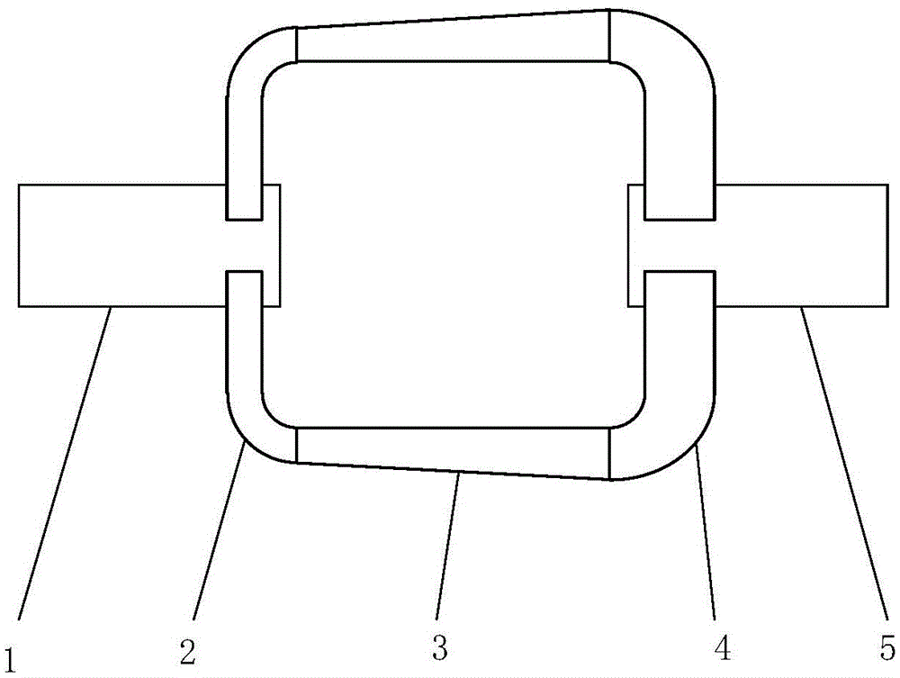
[0017] The circular waveguide TM01-TE01 mode converter of the present invention has a structure as follows figure 1 As shown, it mainly includes input circular waveguide 1, output circular waveguide 5 and various rectangular waveguide components connected between them. Firstly, the radius dimensions of the input circular waveguide 1 and the output circular waveguide 5 are selected to ensure that the TM02 mode and higher order modes are cut-off modes at the operating frequency. The left end of the input circular waveguide 1 is used to feed microwave energy whose mode is TM01 mode, and the right end of the input circular waveguide 1 is short-circuited. Preferably, in this embodiment, six identical rectangular E-plane 90-degree curved waveguides 2 are coupled and connected to the input circular waveguide 1 at equal intervals in the circumferential direction along the side of the input circular waveguide 1 with a certain distance from the short-circuit surface. At the coupling po...


PUM


Abstract

The invention discloses a compact circular waveguide TM01-TE01 mode converter, and aims to provide the mode converter from a circular waveguide TM01 mode to a circular waveguide TE01 mode, wherein the mode converter has a compact structure, and the input and the output of the mode converter are on the same straight line. The mode converter mainly comprises an input circular waveguide (1) for propagating the TM01 mode, an output circular waveguide (5) for propagating the TE01 mode, N rectangular E-surface 90-degree bending waveguides (2), N rectangular 90-degree twisted waveguides (3) and N rectangular H-surface 90-degree bending waveguides (4), wherein N is an even number greater than 3. According to the mode converter, the two circular waveguides for propagating the TM01 mode and the TE01 mode separately are coaxially arranged; the adjacent one surfaces on the inner sides of the two circular waveguides are short-circuit surfaces; the two circular waveguides are in coupling connection through a series of rectangular waveguide assemblies with even-number columns, wherein the rectangular waveguide assemblies are connected in sequence, and the side faces of the rectangular waveguide assemblies are arranged at the equal intervals; the mode converter is compact in structure, small in size and light in weight; the mode converter adopts an axial symmetrical structure, and the input and the output are arranged on the same axial line, so that the mode purity of the output TE01 mode is improved.

Description

technical field [0001] The invention belongs to the field of microwave waveguide technology, and relates to a circular waveguide mode converter. Background technique [0002] The TE01 mode of the circular waveguide not only has the advantage of small long-distance transmission loss, but also is suitable as the working mode of the rotary joint. However, at present, many high-power microwave sources, such as relativistic return wave tubes, and magnetic insulated wire oscillators use circular waveguides for their output. TM01 mode, so in practical applications, it is necessary to convert the TM01 mode of the circular waveguide into the TE01 mode. [0003] At present, the existing circular waveguide mode conversion method from TM01 to TE01 uses a segmented conversion structure to realize the mode conversion, and its structure is as follows figure 1 shown. This structure first converts the circular waveguide TM01 mode into the circular waveguide TE11 mode, then converts the TE1...

Claims


Application Information

Patent Timeline
IPC IPC(8): H01P1/16
CPCH01P1/163
Inventor 黄惠军王效顺吴江牛王杉方进勇
Owner XIAN INSTITUE OF SPACE RADIO TECH
Learn More