
Permanent magnetic synchronous generator rotor for wind power generation

A generator rotor, permanent magnet synchronous technology, applied in the direction of magnetic circuit rotating parts, magnetic circuit, electrical components, etc., can solve the problems of tight development tasks, late research and application start, and technical difficulties, and achieve anti-vibration capabilities. High efficiency, high reliability, light weight, good application prospects

Inactive Publication Date: 2016-04-13
STATE GRID GASU ELECTRIC POWER RES INST +2
View PDF1 Cites 4 Cited by
  • Summary
  • Abstract
  • Description
  • Claims
  • Application Information

AI Technical Summary

Problems solved by technology

The high coercive force of rare earth permanent magnets, especially high intrinsic coercive force and high magnetic energy product can make rare earth permanent magnet synchronous generators have higher reliability and light weight under the same conditions, and are suitable for high power in the field of wind power generation The technical requirements of density generators, domestic research and application in this field started relatively late, the development task is tight and the technology is difficult

Method used


Image

  • Permanent magnetic synchronous generator rotor for wind power generation

Examples


Embodiment Construction

[0023] In order to clearly understand the technical solution of the present invention, its detailed structure will be presented in the following description. Obviously, the implementation of the embodiments of the invention is not limited to specific details familiar to those skilled in the art. The preferred embodiments of the present invention are described in detail below, and there may be other implementations besides those described in detail.

[0024] The present invention will be described in further detail below in conjunction with the accompanying drawings and embodiments.

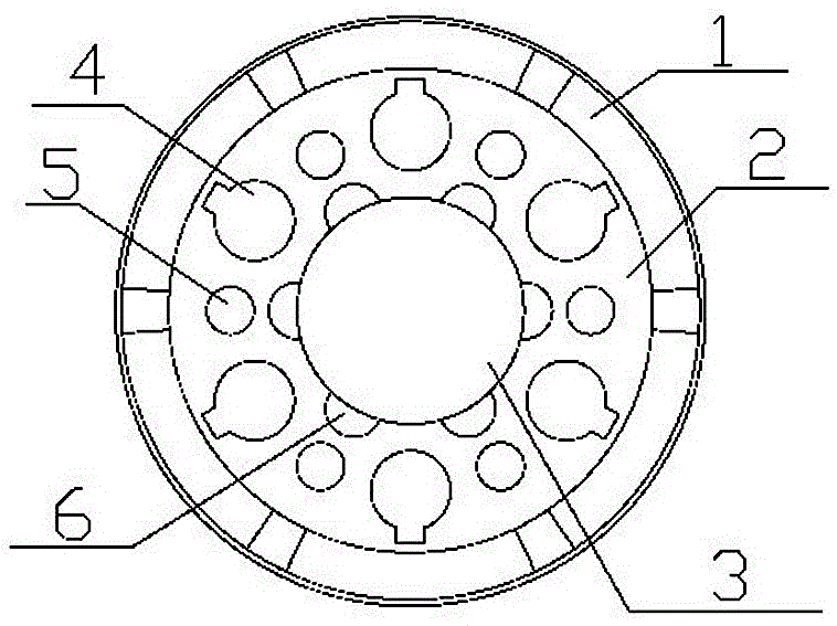
[0025] The permanent magnet synchronous generator rotor used for wind power generation in the embodiment of the present invention is high reliability and high power, such as figure 1 As shown, it includes a permanent magnet magnetic steel 1, a rotor iron core 2 and a rotating shaft 3, and is characterized in that it also includes a first hole slot 4 and an air groove 6; the permanent magnet magne...


PUM


Abstract

The invention discloses a permanent magnetic synchronous generator rotor for wind power generation. The permanent magnetic synchronous generator rotor comprises permanent magnetic steel bars, a rotor core and a rotating shaft. The permanent magnetic synchronous generator rotor further comprises first hole slots and air slots. The permanent magnetic steel, the rotor core and the rotating shaft are successively distributed in a clinging manner from outside to inside in one circumferential axis. The rotating shaft is a solid shaft. Hot interference fit is utilized between the rotating shaft and the circumference which engages with the rotor core. Furthermore one side circumference of the rotor core is provided with a plurality of semicircular air slots. The central circumference between the outer diametric plane and the inner diametric plane of the rotor yoke is provided with a plurality of circular first hole slots. The number of the first hole slots is equal with that of the permanent magnetic steel bars. Furthermore the center of each first hole slot is in the central axis of each magnetic steel bar. The permanent magnetic synchronous generator rotor satisfies technological requirements of small weight, high control flexibility, simple structure, high vibration resistance, high efficiency and high reliability in a power generator in a wind power generation field.

Description

technical field [0001] The invention belongs to the technical field of wind power generation, and in particular relates to a permanent magnet synchronous generator rotor for wind power generation. Background technique [0002] In recent years, with the rapid development of wind power generation system, its proportion in electric energy is increasing day by day. Wind turbines have strict requirements on grid-connected reliability, weight, and economic benefits. High reliability, light weight, and large output per unit volume are the basic requirements for various types of generators in the field of wind power generation. The high coercive force of rare earth permanent magnets, especially high intrinsic coercive force and high magnetic energy product can make rare earth permanent magnet synchronous generators have higher reliability and light weight under the same conditions, and are suitable for new power grid regulations Regarding the technical demand for wind turbines, do...

Claims


Application Information

Patent Timeline
Patent Type & Authority Applications(China)
IPC IPC(8): H02K1/27H02K1/32
CPCH02K1/2706H02K1/32H02K2213/03
Inventor 包艳艳陈博栋樊新鸿牛欢欢贾婷婷邵伟明
Owner STATE GRID GASU ELECTRIC POWER RES INST
Learn More