A cross-folding friction generator

A friction generator, folding technology, applied in the direction of friction generators, etc., can solve the problems of low output power, limited application, AC output and output instability, etc., and achieve the effect of high output voltage, simple circuit design, and simple structure

Inactive Publication Date: 2017-07-11
HENAN NORMAL UNIV
View PDF2 Cites 2 Cited by
  • Summary
  • Abstract
  • Description
  • Claims
  • Application Information

AI Technical Summary

Problems solved by technology

[0004] The existing triboelectric nanogenerators have problems such as low output power, AC output and output instability, which limit their application in real life

Method used


Image

  • A cross-folding friction generator
  • A cross-folding friction generator
  • A cross-folding friction generator

Examples


Embodiment Construction

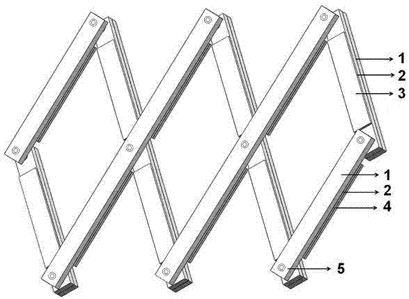
[0023] The present invention will be described in detail below in conjunction with the accompanying drawings. Such as figure 1 As shown, a cross-folding friction generator includes at least one first friction unit, at least one second friction unit, a rotating shaft 5 connecting the first friction unit and the second friction unit, and a pad arranged at the rotating shaft 5 plate; the first friction unit includes a base 1, a metal electrode plate 2 arranged on the base 1 and a first friction layer 3 filled on the metal electrode plate 2, and the second friction unit includes a base 1, a metal electrode plate 2 arranged on the base The metal electrode plate 2 on 1 and the second friction layer 4 filled on the metal electrode plate 2, the first friction unit and the second friction unit are crossed and stacked together through the rotating shaft 5 hinged at the center of the base to form a power generation unit, And the first friction layer 3 of the first friction unit is oppos...


PUM


Abstract

The invention discloses a cross-folding friction generator, which comprises at least one friction unit, at least one second friction unit, a rotating shaft and a base plate, wherein the rotating shaft is connected with the first friction unit and the second friction unit; the base plate is arranged on the rotating shaft; the first friction unit comprises a base, a metal electrode plate and a first friction layer; the metal electrode plate is arranged on the base; the first friction layer is filled into the metal electrode plate; the second friction unit comprises a base, a metal electrode plate and a second friction layer; the metal electrode plate is arranged on the base; the second friction layer is filled into the metal electrode plate; the first friction unit and the second friction unit are crossly and oppositely stacked together through the rotating shaft hinged with the centers of the bases to form a power generation unit; and the first friction layer of the first friction unit and the second friction layer of the second friction unit are oppositely arranged. The cross-folding friction generator has the advantages of being simple in structure, low in cost, durable, high in output voltage, high in current, easy to popularize and the like.

Description

technical field [0001] The invention belongs to the technical field of generators, and in particular relates to a cross-folding friction generator. Background technique [0002] At present, the whole world is facing the dual pressure of conventional energy shortage and environmental protection. In order to alleviate the current energy pressure, the development and application of new generators are urgently needed. The form of power generation that is less damaging to the environment and consumes less natural resources has become the best choice for sustainable development, and has important practical significance for protecting the environment and saving energy. In addition, the development of micro self-propelled systems and portable electronic devices not only requires generators to have higher power generation efficiency, but also to have smaller mass and volume. There is an urgent need for newer power generation mechanisms and more optimized power generation modes. [...

Claims


Application Information

Patent Timeline
Patent Type & Authority Patents(China)
IPC IPC(8): H02N1/04
CPCH02N1/04
Inventor 高书燕郑昕魏献军苏景振王中林
Owner HENAN NORMAL UNIV
Why Eureka
Try Eureka