Improved low-resistance injector

A technology of low-resistance syringes and top caps, applied in the direction of hypodermic injection devices, etc., which can solve problems such as the inability to mass-produce on a large scale, the inability to effectively reduce the frictional resistance between the piston and the barrel wall, and the inability to automatically adjust the sealing degree of the piston and the barrel wall, etc. question

Active Publication Date: 2016-04-20
余利荣
View PDF7 Cites 8 Cited by
  • Summary
  • Abstract
  • Description
  • Claims
  • Application Information

AI Technical Summary

Problems solved by technology

Another example: Chinese patent 95193831.2 (publication number: CN1152882A, publication date: June 25, 1997) discloses a "low resistance syringe". The wall is pulled apart to reduce the friction between the piston and the barrel wall, but these syringes cannot automatically adjust the sealing degree between the piston and the barrel wall with the change of the pressure in the barrel, and cannot effectively reduce the frictional resistance between the piston and the barrel wall , can not achieve better results
In addition, although some syringes can achieve the desired effect, this kind of syringe has high requirements on mold precision, and the production process of rubber vulcanization is difficult. When the friction resistance is 0.1 (Newton), the failure rate of the product is more than 1 / 10,000. Cannot meet industry standards and cannot be mass-produced on a large scale

Method used


Image

  • Improved low-resistance injector
  • Improved low-resistance injector
  • Improved low-resistance injector

Examples


Embodiment Construction

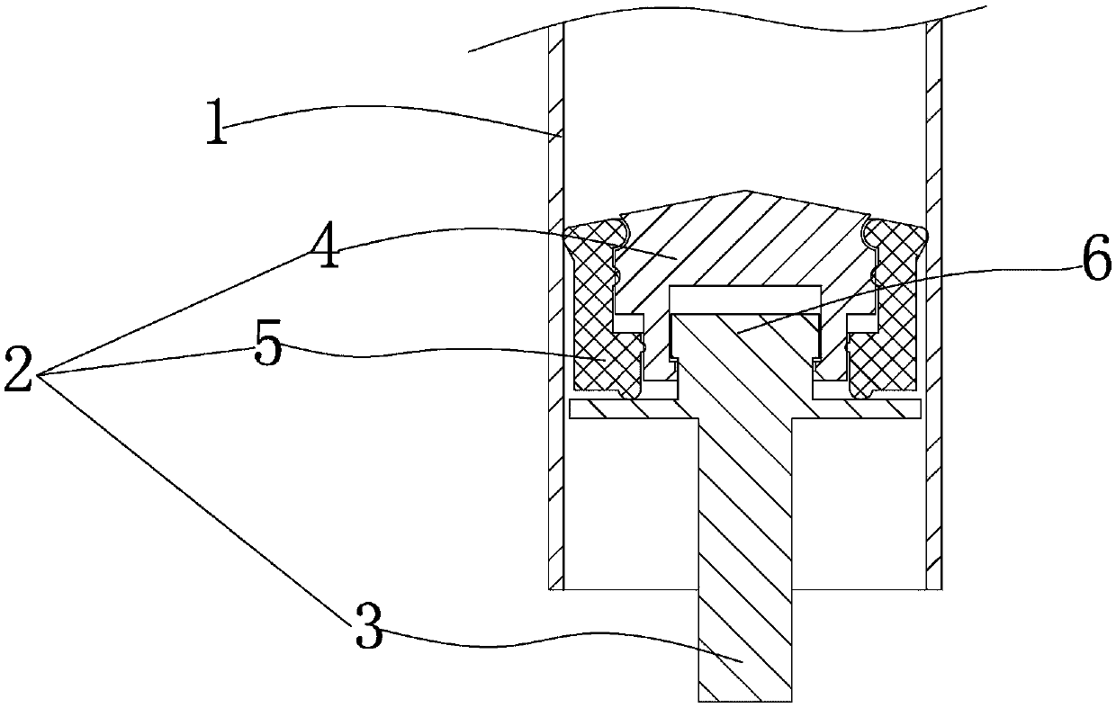
[0019] see figure 1 , an improved low-resistance syringe, comprising a syringe 1, a piston 2, the piston 2 is composed of a push rod 3, a top cap 4, and a rubber plug 5, the top cap 4 is installed on the installation head 6 at the front end of the push rod, and the rubber plug 5 Put it on top cap 4.

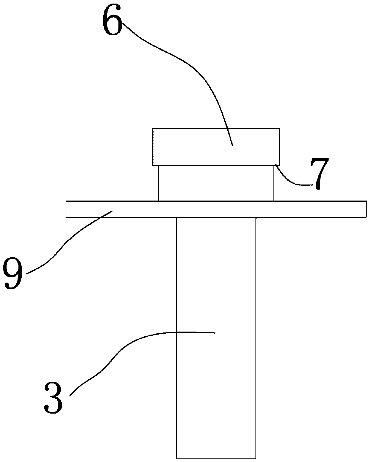
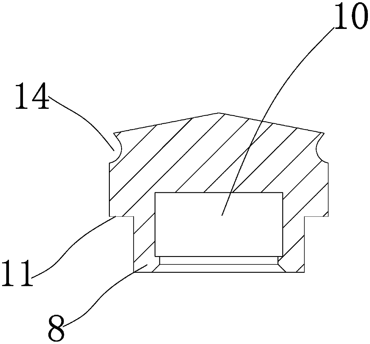
[0020] see figure 2 , image 3 , Figure 4 , The mounting head 6 of the push rod is provided with a shoulder 7, and correspondingly, the lower part of the top cap 4 is provided with a clamping foot 8 matched with the shoulder 7. The cooperation between the shoulder 7 and the clamping foot 8 can make the top cap 4 and the push rod 3 lock each other firmly without slipping off. The position where the push rod is located below the rubber plug is formed with a push plate 9, which can easily push the rubber plug 5. The top cap 4 is provided with an inner cavity 10 for placing the push rod installation head 6. In the initial state, there is a gap between the top of the installatio...


PUM


Abstract

An improved low-resistance injector comprises a needle cylinder and a piston. The improved low-resistance injector is characterized in that the piston is composed of a push rod, a top cap and a rubber plug. The top cap is installed on an installation head at the front end of the push rod. The top cap is sleeved with the rubber plug. A push plate is formed at the portion, below the rubber plug, of the push rod. The top cap is provided with an inner cavity for containing the installation head of the push rod. In the initial state, a gap is reserved between the top cap and the top end of the installation head, and correspondingly, a gap is reserved between the bottom of the top cap and the push plate of the push rod. An upper shoulder is arranged on the top cap. A lower shoulder corresponding to the upper shoulder is arranged inside the rubber plug. In the initial state, the gap is reserved between the upper shoulder and the lower shoulder. An inner adjustment sealing ring is integrally formed on the inner circumferential face of the upper portion of the rubber plug. A semicircular groove where the inner adjustment sealing ring can be embedded is formed in the outer circumferential face of the top cap correspondingly. An outer sealing ring is integrally formed on the outer circumferential face of the upper portion of the rubber plug.

Description

technical field [0001] The invention relates to a medical syringe, in particular to a low-resistance syringe capable of reducing the frictional resistance between the inner wall of the syringe barrel and the sliding piston inside. Background technique [0002] Syringes are an indispensable tool in medical treatment, especially in the field of anesthesia punctures. The known epidural anesthesia puncture kits still use glass syringes, and their injection cylinders are made of glass. The disadvantages of this glass syringe It is easy to break during transportation. Because the push rod is frosted, the glass shavings cannot be cleaned thoroughly, and the copper core is out of round, which will cause liquid leakage, resulting in unsatisfactory use. If the injection cylinder is replaced by other materials, in order to prevent To obtain a good leak-proof sealing effect, the piston must press against the inner wall of the cylinder. If the interference between the cylinder and the pi...

Claims


Application Information

Patent Timeline
Patent Type & Authority Applications(China)
IPC IPC(8): A61M5/315
CPCA61M5/31513A61M5/31515
Inventor 余利荣
Owner 余利荣
Why Eureka
Try Eureka