Tubular synergistic layer and desulfurizing tower provided with the same
A desulfurization tower and tube-type technology, applied in the field of separation devices, can solve the problems of poor load adaptability of desulfurization tower, increased risk of absorption tower, and damage to tray holes, etc., to facilitate manual installation, good desulfurization and dust removal effects, and reduce production costs Effect
- Summary
- Abstract
- Description
- Claims
- Application Information
AI Technical Summary
Problems solved by technology
Method used
Image
Examples
Embodiment 1
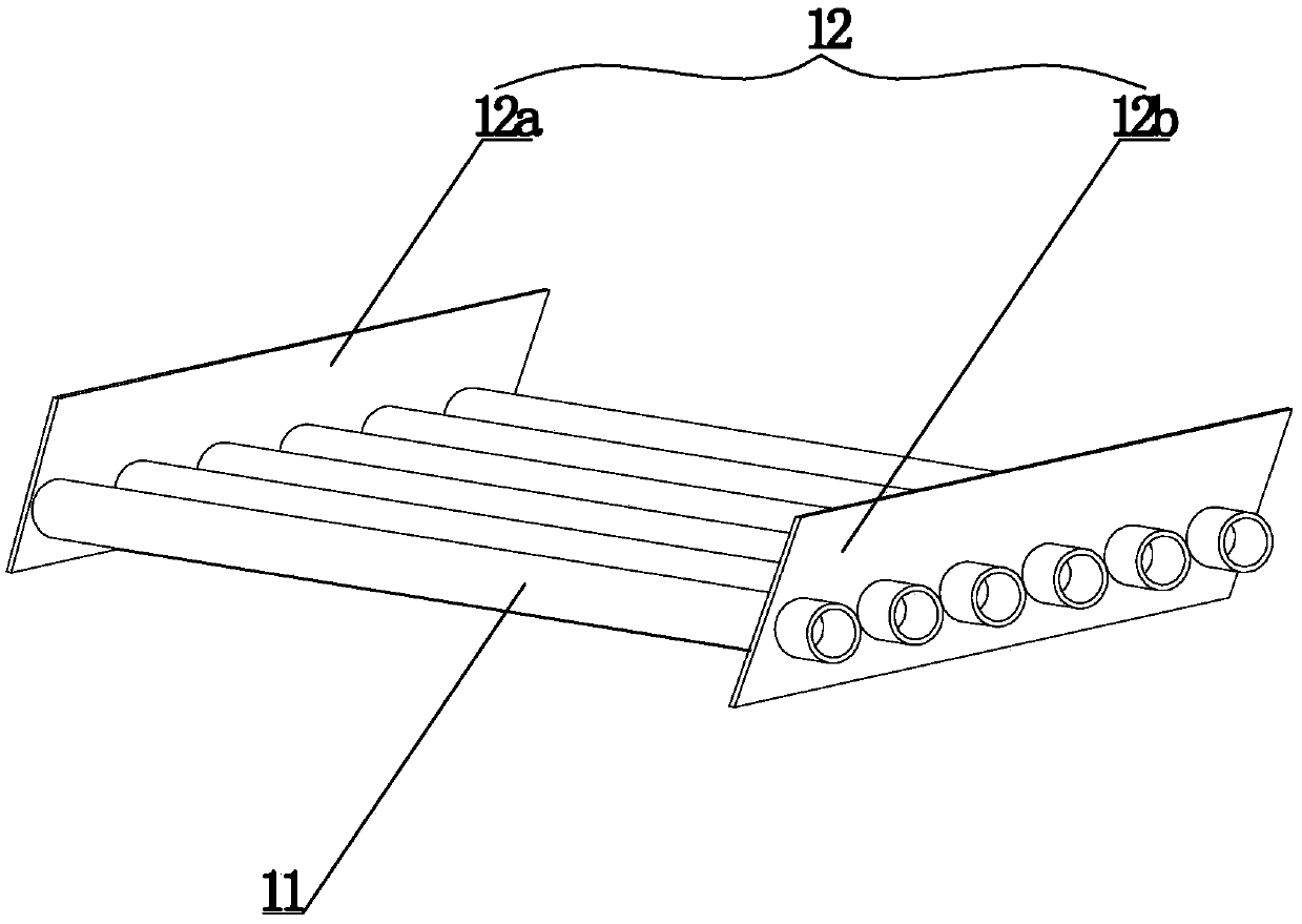
[0033] In this embodiment, the tubular synergistic layer, combined with figure 1 , comprising a synergistic tube 11 and a side plate 12, the synergistic tube 11 is provided with a layer, the side plate 12 includes an end side plate 12a and an end side plate 2 12b, and the end side plate 12a and the end side plate 2 12b are respectively installed on the booster effect pipe 11 two ends. Specifically in this embodiment, the side plates 12 are vertically fitted on the booster tube 11; the booster tube 11 is a cylindrical structure with both ends sealed.
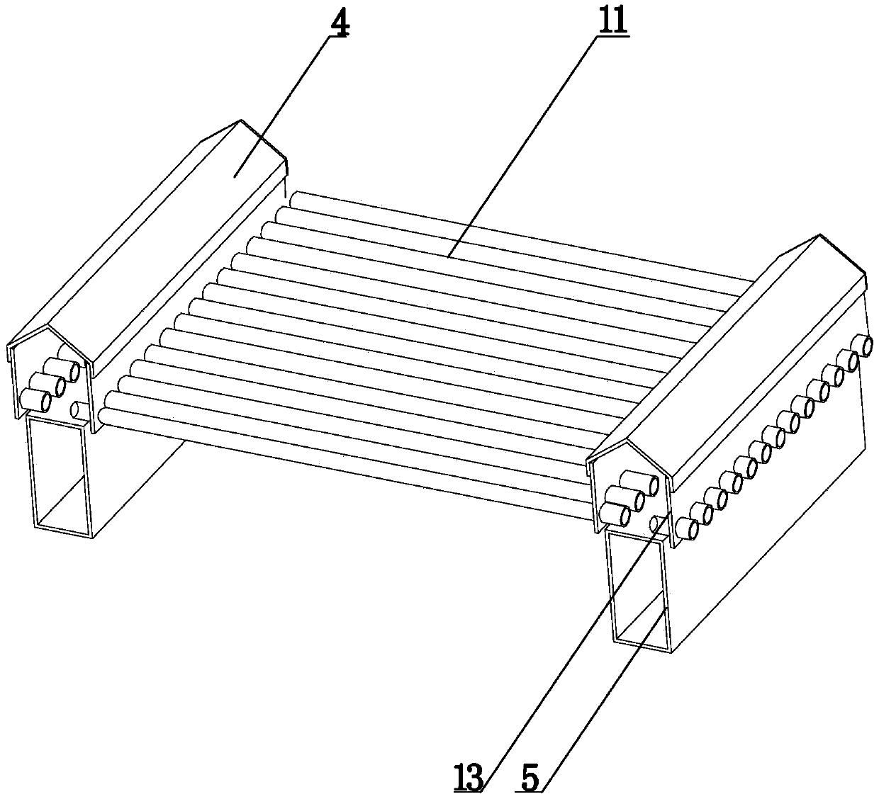
[0034] Apply the above efficiency tube to the desulfurization tower, combined with image 3 , the formed desulfurization tower includes a tower body 2, a spray layer 3 and a tubular synergistic layer 1, and the spray layer 3 is provided with two layers, which are respectively called the bottom spray layer 3a and the second bottom spray layer 3b. Figure 7 , the tubular synergistic layer 1 is installed below the bottom spray lay...
Embodiment 2
[0042] The setting and working principle of this embodiment are the same as that of Embodiment 1, the difference is that: in combination Figure 8 , the synergistic layer 1 is set between the bottom spray layer 3a and the sub-bottom spray layer 3b, the upward flue gas is firstly treated by the bottom spray layer 3a, and then processed by the tubular synergistic layer 1 to strengthen the treatment effect , and then continue to carry out the spray treatment of the sub-bottom spray layer 3b.
Embodiment 3
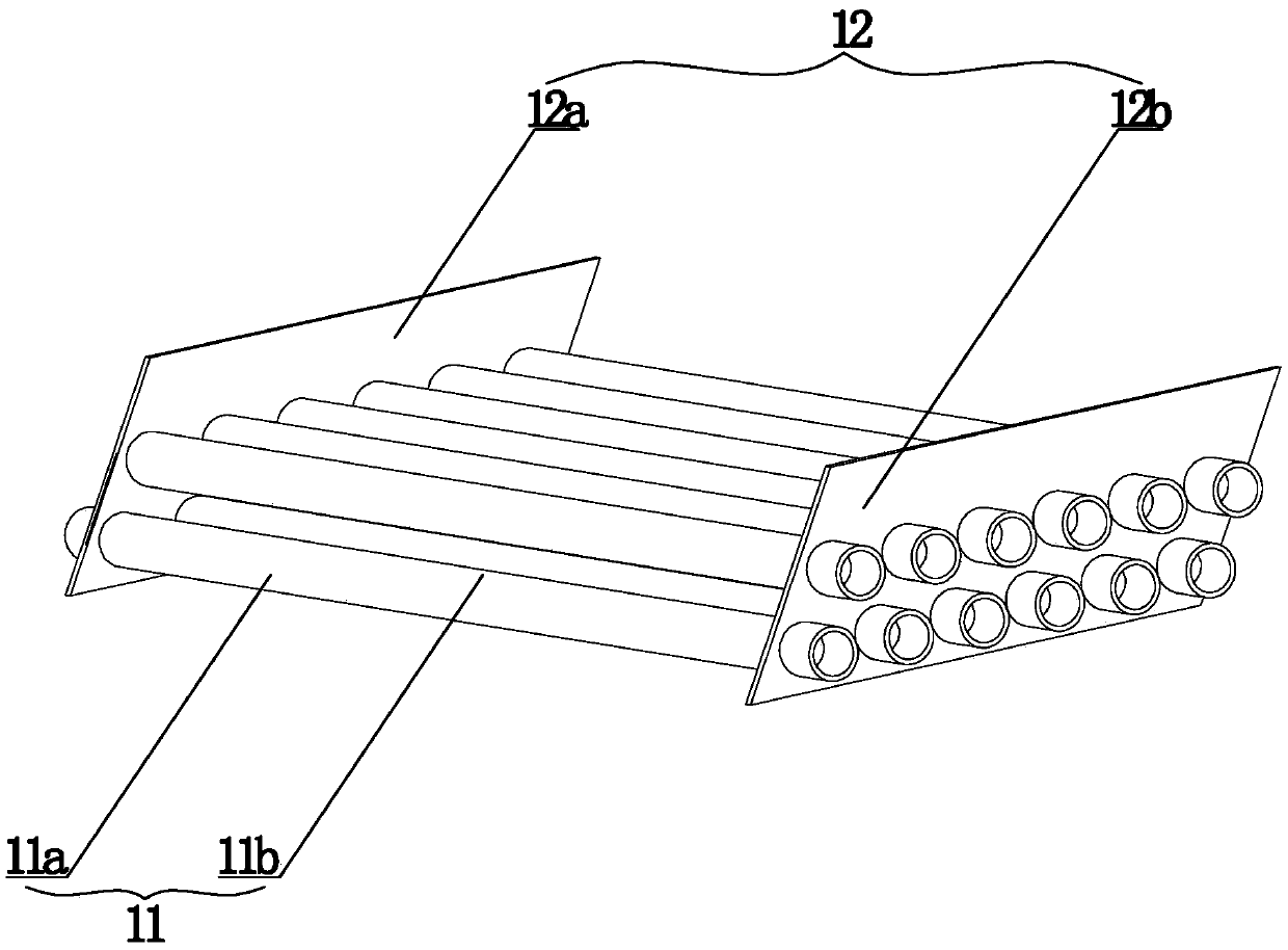
[0044] In this embodiment, the tubular synergistic layer is combined with figure 2 , including a booster tube 11, a support and a side plate 12, the booster tube 11 is provided with a layer, and the side plate 12 includes end side plate 1 12a and end side plate 2 12b and is located at end side plate 1 12a, end side plate 2 12b The middle side plates are evenly arranged, and the first end side plate 12a and the second end side plate 12b are installed at both ends of the efficiency tube 11. Specifically in this embodiment, the side plate 12 is vertically set on the booster tube 11; the booster tube 11 is a cylindrical structure, and its two ends are sealed; the booster tube 11 is provided with two layers, which are booster tubes The first 11a and the second booster tube 11b; the first booster tube 11a and the second booster tube 11b are parallel to each other, and the first booster tube 11a and the second booster tube 11b are located between the two supports 13 .
[0045] Appl...
PUM
 Abstract
Description
Claims
Application Information
 - R&D
- Intellectual Property
- Life Sciences
- Materials
- Tech Scout
- Unparalleled Data Quality
- Higher Quality Content
- 60% Fewer Hallucinations
Browse by: Latest US Patents, China's latest patents, Technical Efficacy Thesaurus, Application Domain, Technology Topic, Popular Technical Reports.
© 2025 PatSnap. All rights reserved.Legal|Privacy policy|Modern Slavery Act Transparency Statement|Sitemap|About US| Contact US: help@patsnap.com


