Pneumatic clamping device

A pneumatic clamping and cylinder device technology, which is applied in clamping devices, positioning devices, clamping, etc., can solve problems such as uneven force points of parts, waste of machine tools, and low processing efficiency, so as to improve production efficiency and quality problems , Improve clamping and processing speed, and improve processing efficiency

Inactive Publication Date: 2016-04-20
沈阳兴华航空电器有限责任公司
View PDF6 Cites 3 Cited by
  • Summary
  • Abstract
  • Description
  • Claims
  • Application Information

AI Technical Summary

Problems solved by technology

[0002] At present, the CNC machining center machine tool in the electrical connector industry adopts the manual single-clamp clamping method, which has low processing efficiency. The processing method uses a three-jaw chuck to clamp one piece at a time. The working stroke of the machine tool is not fully utilized, and the machine tool is wasted.
Moreover, each time a piece is clamped, the tool needs to be changed two to three times. After a work shift, workers need to frequently clamp parts, and machine tools need frequent tool changes. These are non-cutting times, and the processing efficiency cannot be improved. In addition, the clamping method is as follows: The three-jaw chuck is manually clamped, the labor intensity of the workers is high, and the stress point of the parts is uneven, the clamping force cannot be accurately grasped, and the mandrel is easy to rotate, which often causes the clamping deformation of the parts, and the thin-walled parts are easy to crack. cause parts to be scrapped

Method used


Image

  • Pneumatic clamping device
  • Pneumatic clamping device
  • Pneumatic clamping device

Examples


Embodiment 1

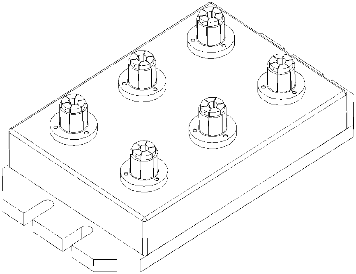
[0026] The pneumatic clamping device is composed as follows: chuck device 1, upper box body 2, cylinder device 3 and lower base plate 4; the number of chuck devices 1 is 4-8 to ensure convenient clamping, parts do not interfere with each other, and do not Affect the tool change without exceeding the stroke. The chuck device 1 is installed on the upper box body 2, and the upper box body 2 is connected to the lower floor 4 upper side, and the chuck device 1 is connected with the cylinder device 3, and the cylinder device 3 is positioned in the upper box body 2 on the base plate 4 upper side.

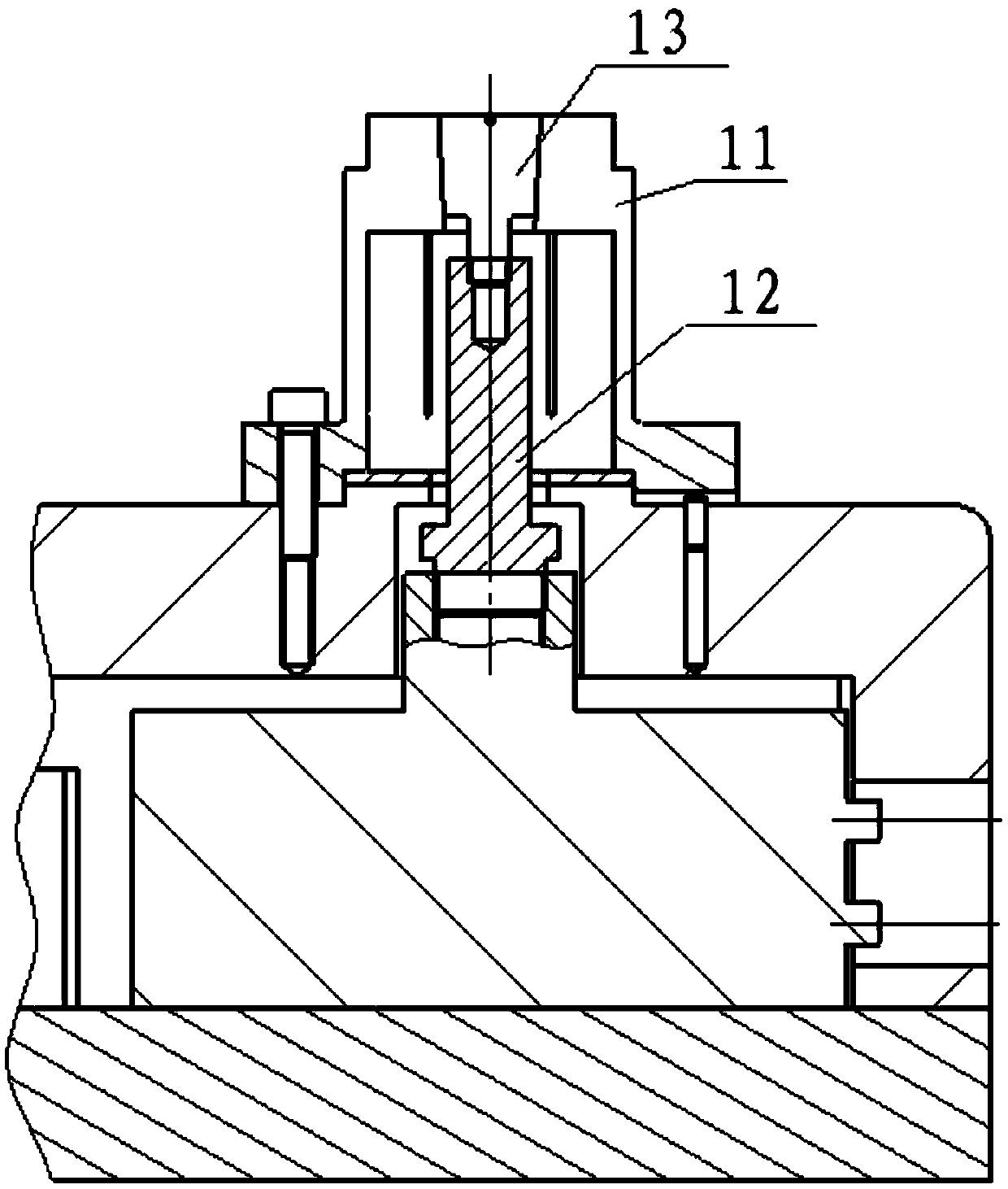
[0027] Described chuck device 1 is constituted as follows: circlip 11, piston rod 12, cone 13, described circlip 11 is installed on the upper box body 2, and circlip 11 is connected with cylinder device 3 by piston rod 12 and cone 13 . Circlip 11 is an expansion circlip, and mandrel and jacket are no longer used to save material. Design circlips of different sizes, and each part correspo...

Embodiment 2

[0037] The pneumatic clamping device is composed as follows: chuck device 1, upper box body 2, cylinder device 3 and lower base plate 4; the number of chuck devices 1 is 6 to ensure convenient clamping, parts do not interfere with each other, and do not affect replacement. Knife, not beyond the stroke. The chuck device 1 is installed on the upper box body 2, and the upper box body 2 is connected to the lower floor 4 upper side, and the chuck device 1 is connected with the cylinder device 3, and the cylinder device 3 is positioned in the upper box body 2 on the base plate 4 upper side.

[0038] Described chuck device 1 is constituted as follows: circlip 11, piston rod 12, cone 13, described circlip 11 is installed on the upper box body 2, and circlip 11 is connected with cylinder device 3 by piston rod 12 and cone 13 . Circlip 11 is an expansion circlip, and mandrel and jacket are no longer used to save material. Design circlips of different sizes, and each part corresponds t...


PUM


Abstract

The invention discloses a pneumatic clamping device which is composed of chuck devices (1), an upper box (2), a cylinder device (3) and a lower bottom plate (4). The number of the chuck devices (1) is 4-8, the chuck devices (1) are installed on the upper box (2), the upper box (2) is connected with the upper side of the lower bottom plate (4), the chuck devices (1) are connected with the cylinder device (3), and the cylinder device (3) is located in the upper box (2) on the upper side of the lower bottom plate (4). The pneumatic clamping device is designed into a multi-clamping-position pneumatic clamping device, and space of a worktable of a numerical control machining center is used to the largest extent to clamp more parts and achieve one-by-one machining. Clamping is achieved at 4-8 points, electric control and pneumatic control are combined, clamping and machining speed is effectively increased, and accordingly machining efficiency is improved. Work efficiency of the numerical control machining center is improved, quick replacement is achieved, part production quality is improved, and labor intensity of workers is reduced.

Description

technical field [0001] The invention relates to the technical field of structural design and application of a clamping device, and in particular provides a pneumatic clamping device. Background technique [0002] At present, the CNC machining center machine tool in the electrical connector industry adopts the manual single clamping position clamping method, which has low processing efficiency. The processing method uses a three-jaw chuck to clamp one piece at a time, the working stroke of the machine tool is not fully utilized, and the machine tool is wasted. Moreover, each time a piece is clamped, the tool needs to be changed two to three times. After a work shift, workers need to frequently clamp parts, and machine tools need frequent tool changes. These are non-cutting times, and the processing efficiency cannot be improved. In addition, the clamping method is as follows: The three-jaw chuck is manually clamped, the labor intensity of the workers is high, and the stress p...

Claims


Application Information

Patent Timeline
Patent Type & Authority Applications(China)
IPC IPC(8): B23Q3/08
CPCB23Q3/08B23Q3/061B23Q2703/04
Inventor 董鑫龙李宝生杨雪冉红培耿志付立波赵昆郝雪冬李兴顺李文涛高前方
Owner 沈阳兴华航空电器有限责任公司
Why Eureka
Try Eureka