
Pneumatic clamp

A technology of pneumatic clamps and collets, applied in the direction of clamping, clamping devices, manufacturing tools, etc., can solve problems such as uneven stress points of parts, waste of machine tools, and low processing efficiency, so as to improve production efficiency and quality problems, The effect of reducing labor intensity and improving production quality

Inactive Publication Date: 2020-06-16
黄石利佳智能科技有限公司
View PDF0 Cites 0 Cited by
  • Summary
  • Abstract
  • Description
  • Claims
  • Application Information

AI Technical Summary

Problems solved by technology

[0002] At present, the CNC machining center machine tool in the electrical connector industry adopts the manual single-clamp clamping method, which has low processing efficiency. The processing method uses a three-jaw chuck to clamp one piece at a time. The working stroke of the machine tool is not fully utilized, and the machine tool is wasted.
Moreover, each time a piece is clamped, the tool needs to be changed two to three times. After a work shift, workers need to frequently clamp parts, and machine tools need frequent tool changes. These are non-cutting times, and the processing efficiency cannot be improved. In addition, the clamping method is as follows: The three-jaw chuck is manually clamped, the labor intensity of the workers is high, and the stress point of the parts is uneven, the clamping force cannot be accurately grasped, and the mandrel is easy to rotate, which often causes the clamping deformation of the parts, and the thin-walled parts are easy to crack. cause parts to be scrapped

Method used


Image

  • Pneumatic clamp
  • Pneumatic clamp
  • Pneumatic clamp

Examples


Embodiment Construction

[0015] The present invention is described in further detail now in conjunction with accompanying drawing. These drawings are all simplified schematic diagrams, which only illustrate the basic structure of the present invention in a schematic manner, so they only show the configurations related to the present invention.

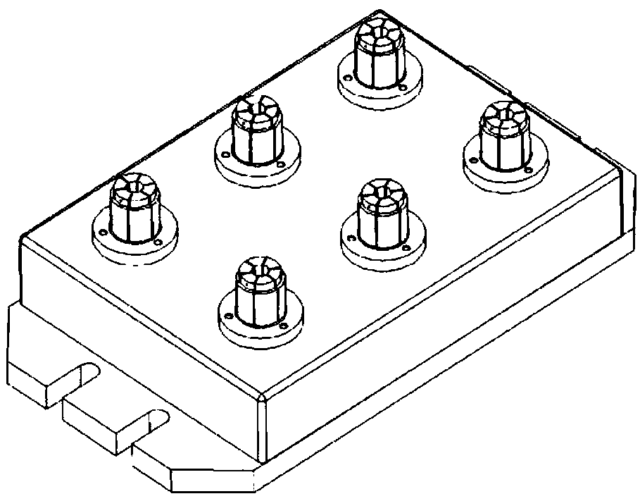
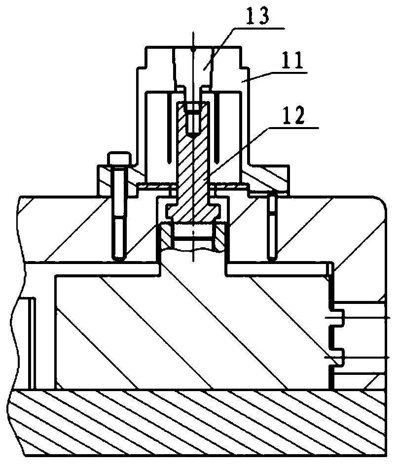
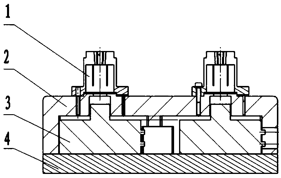
[0016] Figure 1 to Figure 3 A pneumatic clamp shown includes a chuck device 1, an upper box body 2, a cylinder device 3 and a lower base plate 4; the number of chuck devices 1 is 6, which ensures convenient clamping, non-interference between parts, and does not affect replacement. Knife, not beyond the stroke. The chuck device 1 is installed on the upper box body 2, and the upper box body 2 is connected to the lower floor 4 upper side, and the chuck device 1 is connected with the cylinder device 3, and the cylinder device 3 is positioned in the upper box body 2 on the base plate 4 upper side.

[0017] Described chuck device 1 is constituted as follows: circ...


PUM


Abstract

The invention relates to the technical field of automation equipment accessories, in particular to a pneumatic clamp. The pneumatic clamp comprises chuck devices, an upper box body, an air cylinder device and a lower bottom plate, wherein the number of the chuck devices is 2-10, it is guaranteed that clamping is facilitated, parts do not interfere with one another, cutter changing is not affected,and a stroke is not exceeded. The chuck devices are mounted on the upper box body, the upper box body is connected to the upper side of the lower bottom plate, the chuck devices are connected with the air cylinder device, and the air cylinder device is located in the upper box body on the upper side of the bottom plate. According to the pneumatic clamp, the working efficiency of a numerical control machining center is improved, rapid cutter changing is achieved, the part production quality is improved, and the labor intensity of workers is reduced.

Description

technical field [0001] The invention relates to the technical field of automation equipment accessories, in particular to a pneumatic clamp. Background technique [0002] At present, the CNC machining center machine tool in the electrical connector industry adopts the manual single clamping position clamping method, which has low processing efficiency. The processing method uses a three-jaw chuck to clamp one piece at a time, the working stroke of the machine tool is not fully utilized, and the machine tool is wasted. Moreover, each time a piece is clamped, the tool needs to be changed two to three times. After a work shift, workers need to frequently clamp parts, and machine tools need frequent tool changes. These are non-cutting times, and the processing efficiency cannot be improved. In addition, the clamping method is as follows: The three-jaw chuck is manually clamped, the labor intensity of the workers is high, and the stress point of the parts is uneven, the clamping ...

Claims


Application Information

Patent Timeline
Patent Type & Authority Applications(China)
IPC IPC(8): B23Q3/08
CPCB23Q3/061B23Q3/065B23Q3/08B23Q2703/04
Inventor 周铁
Owner 黄石利佳智能科技有限公司
Learn More