Multi-station grinding device for optical lenses
An optical lens, multi-station technology, which is applied in the direction of grinding drive device, optical surface grinder, grinding machine parts, etc. and other problems, to achieve the effect of switching positioning of many stations, improving grinding efficiency, and ensuring the quality of grinding products
- Summary
- Abstract
- Description
- Claims
- Application Information
AI Technical Summary
Problems solved by technology
Method used
Image
Examples
Embodiment 1
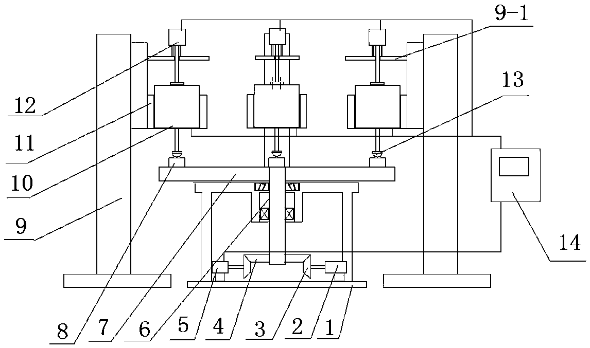
[0021] Such as figure 1 As shown, the optical lens multi-station grinding device of the present invention includes a machine base 1, a turntable 7, at least 2 stations and several lens holders 8 arranged on the turntable 7, and the bottom of the turntable 7 is set to rotate through a central axis 6 Positioning mechanism, the station includes a grinding station and an upper and lower workpiece station, each station is set relative to the central angle of the turntable 7, and at least one grinding mechanism is arranged on the side of the turntable 7. The rotary positioning mechanism can adopt a multi-station switching precision positioning device, specifically, a multi-station switching precision positioning device applied by the applicant of the present invention, including a turntable 7 with a plurality of processing stations on the peripheral side, and a turntable 7 It is connected with the base 1 through tapered roller bearings, ball bearings and a central shaft. The lower ...
Embodiment 2
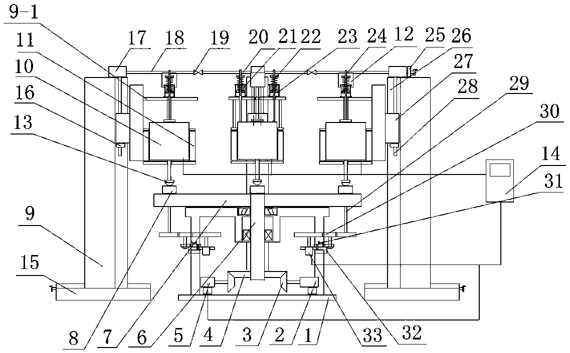
[0025] see figure 2, the multi-station grinding device for optical lenses in this embodiment is an improved technical solution in Embodiment 1, the difference is that: the grinding mechanism can use a flexible control device for the lifting of the grinding head, specifically, the applicant of the present invention can use Another application is a flexible control device for lifting and lowering a grinding head. This device comprises described frame 9, rotary motor 10 and motor sliding sleeve 11, and supporting plate is arranged at the bottom of motor sliding sleeve 11, and rotary motor 10 is positioned at motor sliding sleeve 11 and is slidably matched with it, and rotary motor 10 can be in Lift freely in the motor sliding sleeve 11. The motor sliding sleeve 11 is slidingly connected with the slide rail 26 provided on one side of the frame 9 through the integrated slider 27, the lower end of the main shaft of the rotary motor 10 is connected with the grinding head 13, and th...
PUM
 Abstract
Description
Claims
Application Information
 - R&D
- Intellectual Property
- Life Sciences
- Materials
- Tech Scout
- Unparalleled Data Quality
- Higher Quality Content
- 60% Fewer Hallucinations
Browse by: Latest US Patents, China's latest patents, Technical Efficacy Thesaurus, Application Domain, Technology Topic, Popular Technical Reports.
© 2025 PatSnap. All rights reserved.Legal|Privacy policy|Modern Slavery Act Transparency Statement|Sitemap|About US| Contact US: help@patsnap.com


