Infrared vision based automatic landing guidance method and system applied to fixed-wing UAV (unmanned aerial vehicle)

A technology for automatic landing and unmanned aerial vehicles, which is applied in the direction of aircraft automatic landing aids, aircraft landers, traffic control systems, etc., can solve the problem of insufficient performance of image processors, fast speed of fixed-wing unmanned aerial vehicles, and increased weight of unmanned aerial vehicles and other problems, to achieve the effects of eliminating the influence of visible light, good real-time performance, and reducing the difficulty of recognition

Inactive Publication Date: 2016-04-20
NANJING UNIV OF AERONAUTICS & ASTRONAUTICS
View PDF4 Cites 37 Cited by
  • Summary
  • Abstract
  • Description
  • Claims
  • Application Information

AI Technical Summary

Problems solved by technology

However, at present, the visual guidance schemes designed by many scholars are placed on the UAV, which not only increases the weight of the UAV, but also because of the limited load and insufficient performance of the image processor, it is difficult to satisfy the fast speed of the fixed-wing UAV. The characteristics of high landing accuracy requirements

Method used


Image

  • Infrared vision based automatic landing guidance method and system applied to fixed-wing UAV (unmanned aerial vehicle)
  • Infrared vision based automatic landing guidance method and system applied to fixed-wing UAV (unmanned aerial vehicle)
  • Infrared vision based automatic landing guidance method and system applied to fixed-wing UAV (unmanned aerial vehicle)

Examples


Embodiment Construction

[0036] Embodiments of the present invention are described in detail below, examples of which are shown in the drawings, wherein the same or similar reference numerals denote the same or similar elements or elements having the same or similar functions throughout. The embodiments described below by referring to the figures are exemplary only for explaining the present invention and should not be construed as limiting the present invention.

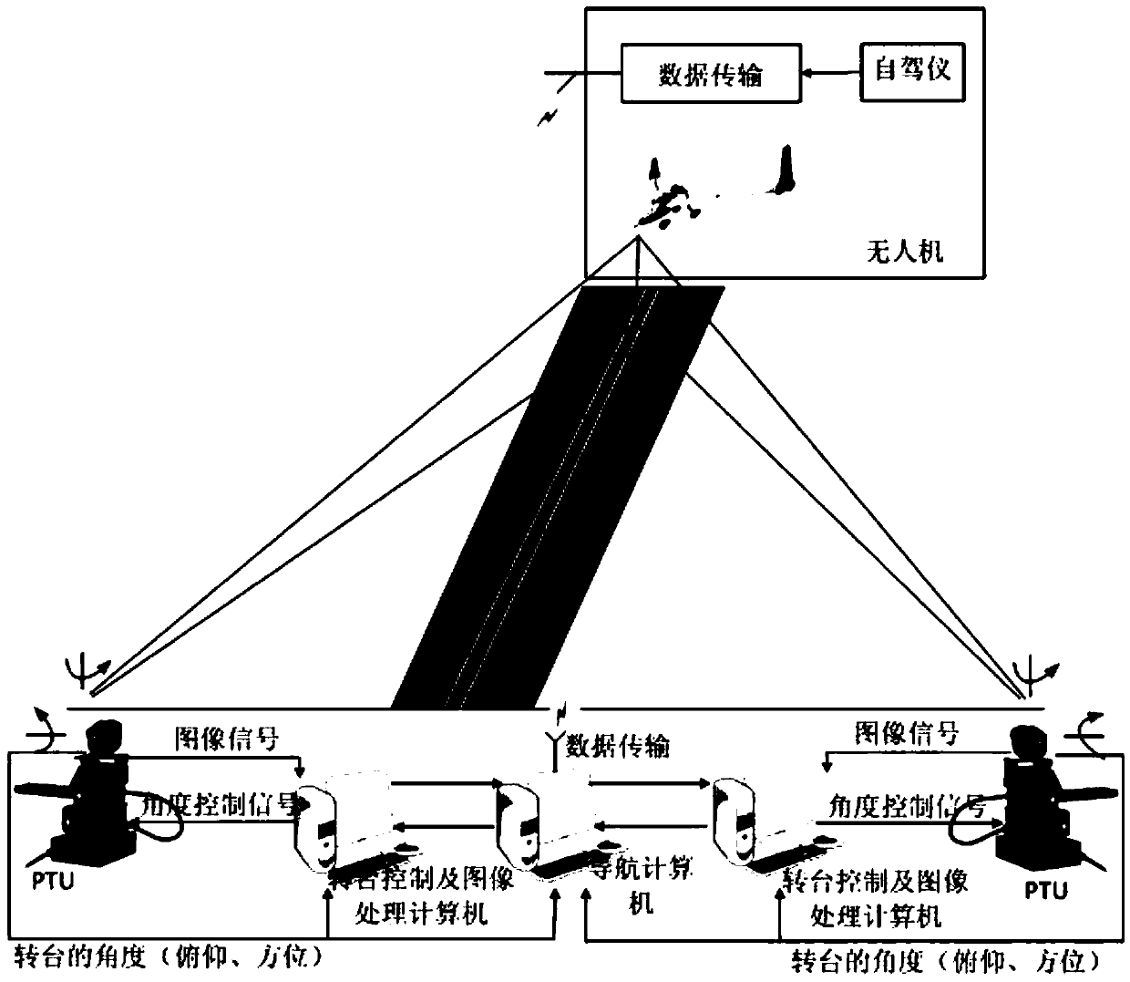
[0037] The automatic landing guidance system of the present invention is made up of two identical image tracking modules, an image processing module, a control module, and a wireless transmission module, wherein the image tracking module is composed of a camera and a high-precision two-axis pan-tilt (PTU) and is placed on the runway respectively On both sides, the camera is installed on the top of the two-axis gimbal, such as figure 1 As shown, the UAV is detected, identified and tracked in the image using image tracking technology, and the...


PUM


Abstract

The invention discloses an infrared vision based automatic landing guidance method and system applied to a fixed-wing UAV (unmanned aerial vehicle). The system comprises two identical image tracking modules, an image processing module, a control module and a wireless transmission module, wherein each image tracking module comprises a camera and biaxial pan-tilt units. According to the method, the UAV is detected, identified and tracked in images with an image tracking technology, and deflecting angles of the pan-tilt units are accurately recorded; the relative space position of the UAV can be determined through geometric relationship analysis and trigonometric calculation of pitch heading angles of the two pan-tilt units and the distance between the pan-tilt units, and position information of the UAV is sent to the UAV through the wireless transmission module, so that the UAV is guided to accurately land. The infrared vision based automatic landing guidance system is constructed on two sides of a landing runway of the UAV, complicated image processing is performed based on powerful computing capacity of a ground-based computer, each guidance device is utilized to the greatest extent, the accuracy of the system is improved, the control is simple, and real-time performance and stability are good.

Description

technical field [0001] The invention relates to an infrared vision-based automatic landing guidance method and system for a fixed-wing unmanned aerial vehicle, belonging to the technical field of navigation, positioning and control. Background technique [0002] Unmanned Aerial Vehicle (UAV) refers to unmanned aerial vehicles, which are mainly used to perform more dangerous tasks such as battlefield reconnaissance, artillery correction, target indication, battlefield surveillance, relay guidance, and electronic countermeasures. Due to the characteristics of short warning time, good concealment, strong reconnaissance ability, long cruising time, low cost, low operational environment requirements, and strong battlefield survivability, UAVs are more and more favored by the armies of various countries and have become the pursuit of military powers. An ideal weapon for "non-contact" and "zero casualties" in modern warfare. [0003] Automatic landing is the most dangerous and dem...

Claims


Application Information

Patent Timeline
Patent Type & Authority Applications(China)
IPC IPC(8): B64F1/00B64D45/04G08G5/02
CPCB64F1/00B64D45/04G08G5/0069G08G5/025
Inventor 吴赛飞王新华徐宽杨铭超
Owner NANJING UNIV OF AERONAUTICS & ASTRONAUTICS
Why Eureka
Try Eureka