Rotary reversing valve and rotary heat-accumulation waste gas incinerator

A technology of a rotary reversing valve and a driving device, applied in the field of machinery, can solve the problems of increased instability, increased manufacturing cost, large contact area, etc., and achieves the effects of simple structure, improved processing efficiency, and simple overall structure

Active Publication Date: 2016-04-20
VERBOCA ENERGY SAVING TECH CO LTD
View PDF9 Cites 10 Cited by
  • Summary
  • Abstract
  • Description
  • Claims
  • Application Information

AI Technical Summary

Problems solved by technology

However, the reversing valve in the prior art, such as the authorized announcement number: CN101603604B rotary switching valve and regenerative gas processing device; There are the following disadvantages: a. The reversing valve rotates frequently, and the rotating surfaces of the plane seal rub against each other. The contact area is large and the friction force is also large, which leads to poor plane seal. The motor drives the entire valve core to rotate, and the energy consumption is also large ; b, the flat seal structure is adopted, in order to prevent excessive wear on the friction surface, there are high requirements in material selection and processing, which virtually increases the manufacturing cost; c, in order to compensate for the wear on the friction surface, replace The directional valve is equipped with compensation mechanisms such as springs and adjusting bolts, which virtually increases the instability of operation

Method used


Image

  • Rotary reversing valve and rotary heat-accumulation waste gas incinerator
  • Rotary reversing valve and rotary heat-accumulation waste gas incinerator
  • Rotary reversing valve and rotary heat-accumulation waste gas incinerator

Examples


Embodiment Construction

[0035] The following will clearly and completely describe the technical solutions in the embodiments of the present invention with reference to the accompanying drawings in the embodiments of the present invention. Obviously, the described embodiments are only some, not all, embodiments of the present invention. Based on the embodiments of the present invention, all other embodiments obtained by persons of ordinary skill in the art without creative efforts fall within the protection scope of the present invention.

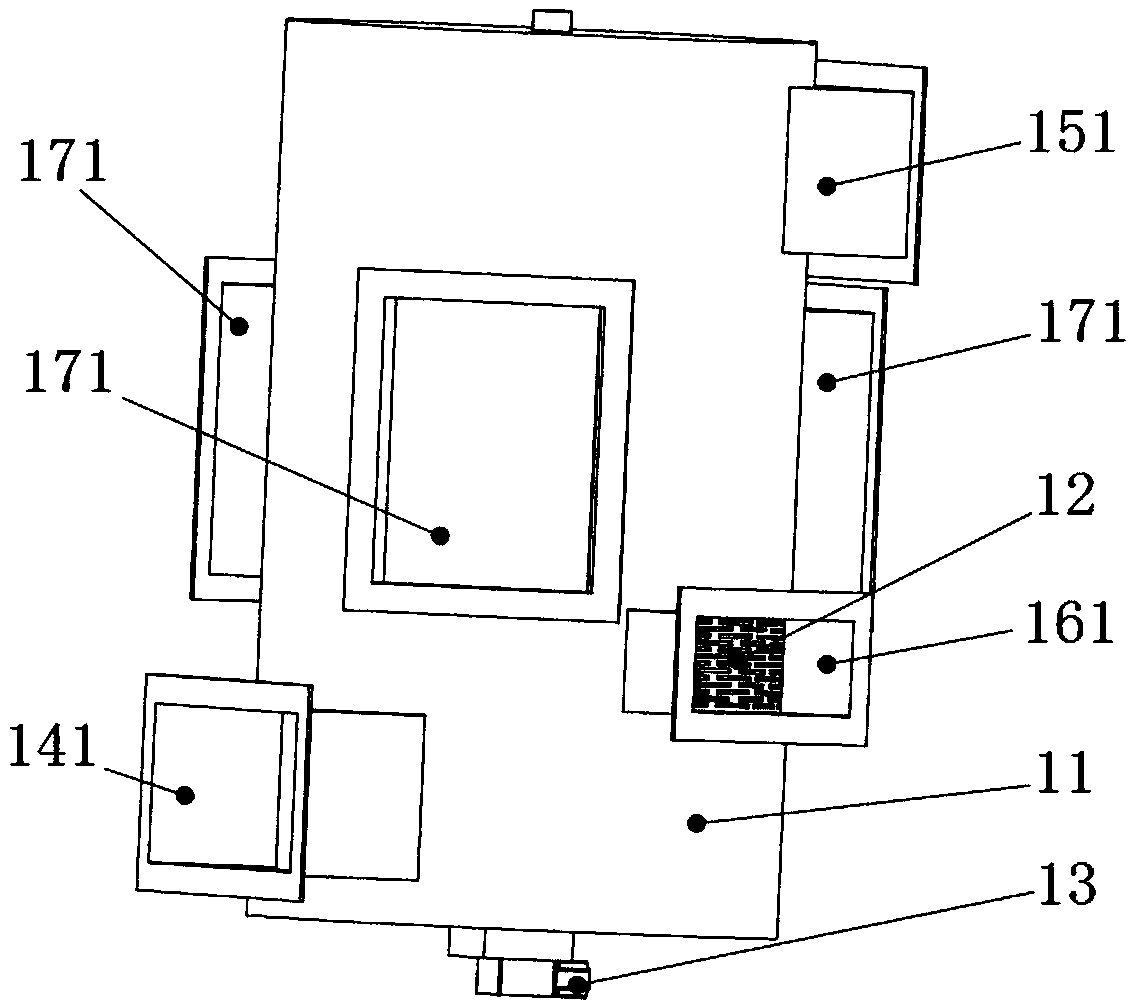
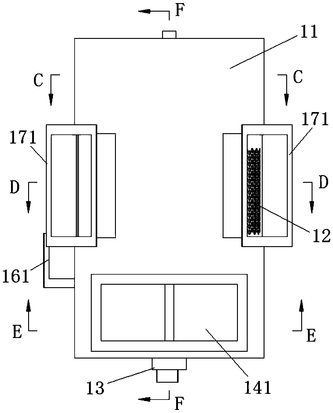
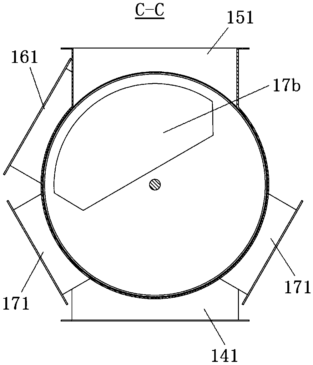
[0036] see Figure 1 to Figure 9 As shown, the present invention is a preferred embodiment of a rotary reversing valve, which includes a valve body 11 , a valve core 12 and a driving device 13 .

[0037] The specific setting form of the rotary reversing valve of the present invention is as follows:

[0038] The valve body 11 is a cylindrical structure with both ends sealed. The central axis of the valve core 12 is installed on the central bearings on the two ends ...


PUM


Abstract

The invention provides a rotary reversing valve which comprises a valve body and a valve core, wherein a clearance is left between the valve body and valve core; the valve core is driven by a drive unit to rotate; a gas inlet region, a gas discharge region, a purging region and at least two distribution regions are arranged between the valve core and valve body; the valve body is provided with a plurality of inlet/outlet ports respectively communicated with all the regions; the distribution regions are respectively a to-be-treated gas distribution region and a treated gas distribution region; the to-be-treated gas distribution region is communicated with the gas inlet region to form a to-be-treated gas passage; the treated gas distribution region is communicated with the gas discharge region to form a treated gas passage; the valve core is in a hollow structure and is communicated with the purging region to form a purging gas passage; and when the purging gas passage is under positive pressure or negative pressure, the purging region obstructs the mutual communication between the to-be-treated gas passage and the treated gas passage. The rotary reversing valve has the advantages of simple structure, low energy consumption, favorable sealability, low cost and the like. The invention also provides a rotary heat-accumulation waste gas incinerator using the rotary reversing valve.

Description

technical field [0001] The invention belongs to the technical field of machinery, and relates to a gas reversing device, in particular to a rotary multi-channel gas reversing valve and a rotary regenerative waste gas incinerator using the gas reversing valve. Background technique [0002] The organic waste gas regenerative incineration device has multiple static pressure chambers, and it is necessary to realize the conversion of air intake, exhaust and purge among the static pressure chambers during operation. If an ordinary cut-off valve is used to realize its conversion, the number of valves is large, and frequent periodic reversing actions will result in short service life of the valve and prone to leakage, and pressure changes at the moment of conversion will cause damage to the subsequent process. The impact causes a series of problems, and the operation control is complicated. The large number of valves will not only increase the cost of equipment, but also reduce the...

Claims


Application Information

Patent Timeline
Patent Type & Authority Applications(China)
IPC IPC(8): F23G7/06F23G5/44
CPCF23G5/44F23G7/06
Inventor 简甦刘清城
Owner VERBOCA ENERGY SAVING TECH CO LTD
Why Eureka
Try Eureka