System and method for testing failure of thermal barrier coating

A test system, thermal barrier coating technology, applied in joint test system, thermal barrier coating failure test system, in-situ dynamic non-destructive real-time online monitoring field, can solve the difficulty of acoustic emission signal analysis, distortion, acoustic emission signal attenuation and other issues to achieve the effect of saving manpower

Inactive Publication Date: 2016-04-20
SHANGHAI INST OF CERAMIC CHEM & TECH CHINESE ACAD OF SCI
View PDF7 Cites 11 Cited by
  • Summary
  • Abstract
  • Description
  • Claims
  • Application Information

AI Technical Summary

Problems solved by technology

[0005] Previous studies on non-destructive characterization of thermal barrier coating failure, especially AE, have mostly focused on normal temperature conditions, such as bending loads (three-point bending, four-point bending, shear), uniaxial loading (tensile Acoustic emission signal detection and analysis under conditions such as heating and compression), the acoustic emission signal detection of coating failure under high temperature conditions is mainly aimed at thermal shock failure in the form of air furnace heating-water quenching, the waveguide rod technology is mainly used to convert the waveguide The rod is welded on the side or back of the tested coating sample, usually a high-temperature alloy or stainless steel substrate, so as to detect the failure process of the coating. The disadvantage of this process is that the length of the waveguide rod is restricted by the experimental device and links, so the acoustic The emission signal will be attenuated and distorted to a certain extent, which brings great difficulties to the analysis of the acoustic emission signal, so it is not easy to judge the "source" information of the coating failure

Method used


Image

  • System and method for testing failure of thermal barrier coating
  • System and method for testing failure of thermal barrier coating
  • System and method for testing failure of thermal barrier coating

Examples


Embodiment Construction

[0051] The present invention will be further described below in conjunction with the drawings and the following embodiments. It should be understood that the drawings and the following embodiments are only used to illustrate the present invention rather than limit the present invention.

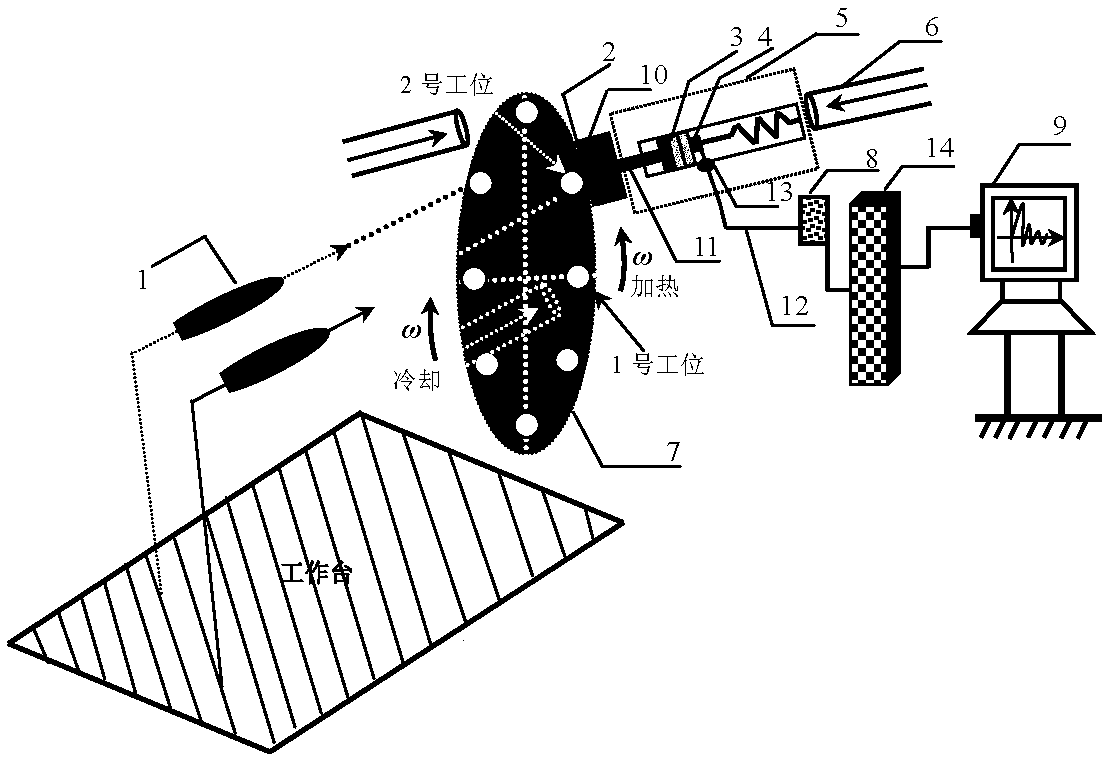
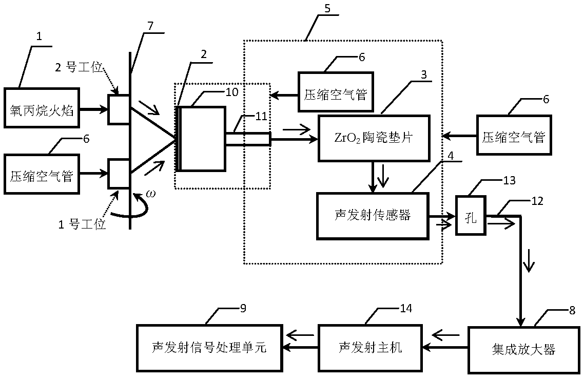
[0052] One of the purposes of the present invention is to solve the prediction of coating failure under high temperature conditions, especially under high temperature and strong heat flux assessment conditions, and then integrate and introduce an acoustic emission signal detection device on the high temperature and strong heat flux cycle thermal assessment device .

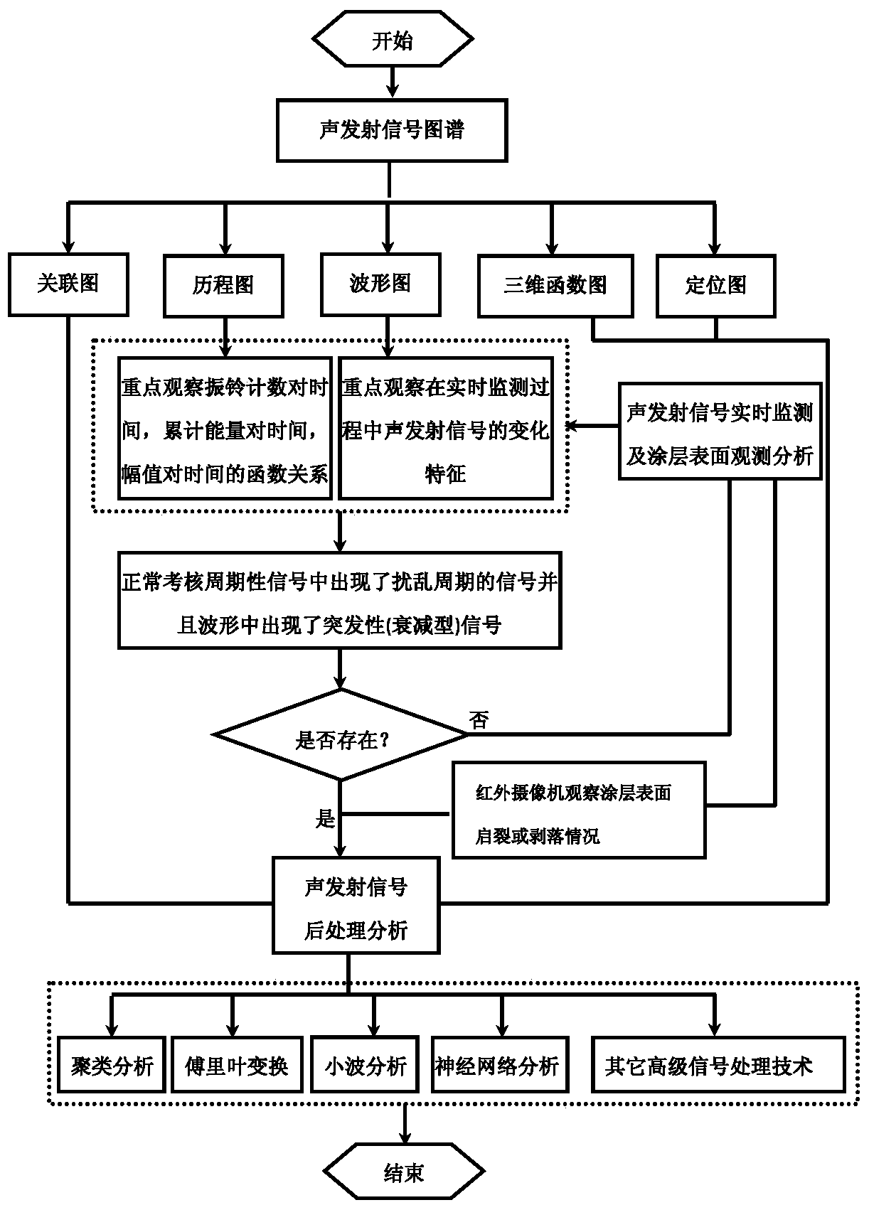
[0053] The second purpose of the present invention is to study the internal mechanism of coating peeling failure under the condition that there is a temperature gradient between the surface and the back of the coating. By analyzing the collected acoustic emission signals, the source information and information of the coating failu...


PUM


Abstract

The invention provides a system and a method for testing the failure of a thermal barrier coating. The system comprises a high-temperature and high-thermal-flux circulating thermal inspection device which is used for detecting the thermal impact life of the coating and is provided with a fixing unit for fixing a coating test sample and a heating unit for cyclically heating the coating test sample, an acoustic emission signal detection device which is used for coating failure and is provided with an acoustic emission sensor for detecting an acoustic emission signal in the coating failing process, and an acoustic emission signal processing unit for receiving and processing the acoustic emission signal from the acoustic emission sensor to forecast a coating destroy critical time point in advance. The system is used for dynamically and non-destructively monitoring the failure of the thermal barrier coating in situ, in real time and on line under the condition of high-temperature and high-thermal-flux circulating thermal impact.

Description

technical field [0001] The present invention relates to the field of performance testing of thermal barrier coatings, in particular, to a testing system and method for thermal barrier coating failure, especially to a thermal barrier coating failure test method for high temperature and high heat flux density cycle thermal shock conditions. A combined test system and test method for in-situ dynamic non-destructive real-time online monitoring. Background technique [0002] The failure of thermal barrier coatings under high temperature conditions has always been a key topic in the research of thermal barrier coatings. The research on the failure modes and mechanisms of thermal barrier coatings will help to judge the failure mode and critical point of service failure of thermal barrier coatings. The failure of thermal barrier coatings under high temperature service conditions is a highly nonlinear process. Its failure mode and critical point of destruction are functions of temp...

Claims


Application Information

Patent Timeline
Patent Type & Authority Applications(China)
IPC IPC(8): G01N17/00
CPCG01N17/00
Inventor 王亮倪金星钟兴华赵华玉邵芳刘晨光庄寅陶顺衍
Owner SHANGHAI INST OF CERAMIC CHEM & TECH CHINESE ACAD OF SCI
Why Eureka
Try Eureka