Signal processing method of mode s transponder based on amplitude comparison and direction finding system

A signal processing and response signal technology, applied in the signal processing field of S-mode transponders, can solve problems such as waste of hardware resources, high transmission power, radio frequency signal interference, etc., to reduce asynchronous crosstalk, reduce transmitter power, and increase detection effect of distance

Active Publication Date: 2017-12-08
CHINA ELECTRONICS TECHNOLOGY AVIONICS CO LTD
View PDF3 Cites 1 Cited by
  • Summary
  • Abstract
  • Description
  • Claims
  • Application Information

AI Technical Summary

Problems solved by technology

[0004] The purpose of the present invention is to provide a signal processing method of an S-mode transponder based on the ratio-amplitude direction-finding system, which solves the problem that the traditional S-mode transponder cannot judge the orientation of the inquiry signal, so that the inquiring device must maintain a higher frequency of repeated inquiries and a relatively high frequency of inquiry. Large transmit power to maintain communication with the airborne transponder, resulting in a large number of radio frequency signal interference in the flight airspace, which has a serious impact on the increasingly busy air traffic control, and the traditional S mode transponder as an independent Individuals cannot share hardware resources and antenna channels with TCAS equipment, resulting in waste of hardware resources and inconvenient ground maintenance and management

Method used


Image

  • Signal processing method of mode s transponder based on amplitude comparison and direction finding system
  • Signal processing method of mode s transponder based on amplitude comparison and direction finding system
  • Signal processing method of mode s transponder based on amplitude comparison and direction finding system

Examples


Embodiment

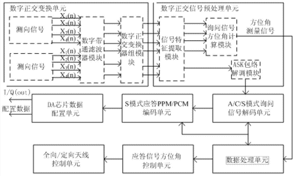
[0036] Such as figure 1 As shown, the mode S response system of the ratio amplitude direction finding system in this embodiment includes a digital orthogonal transform unit, a digital orthogonal signal preprocessing unit, an A / C / S mode interrogation signal decoding unit, and an S mode Response PPM / PCM encoding unit, DA chip data configuration unit, data processing unit, response signal azimuth control unit and omnidirectional / directional antenna control unit;

[0037] The digital orthogonal transformation unit is used to receive the direction finding signal and filter the direction finding signal;

[0038] The digital orthogonal signal preprocessing unit is used for signal feature extraction, query signal azimuth calculation and ASK envelope demodulation of the signal output by the digital orthogonal transform unit;

[0039] The A / C / S mode interrogation signal decoding unit is used to decode the envelope waveform of the interrogation signal output by the digital quadrature signal pre...


PUM


Abstract

The invention discloses an S-mode response system in an amplitude comparison direction-finding system, and the S-mode response system comprises a digital orthogonal transformation unit, a digital orthogonal signal preprocessing unit, an A / C / S mode inquiry signal decoding unit, an S-mode response PPM / PCM coding unit, a DA chip data configuration unit, a data processing unit, a response signal azimuth angle control unit, and an omnidirectional / directional antenna control unit. The S-mode response system can refer to the design thought of a hardware circuit of a comprehensive monitoring system on a radio frequency receiving and transmitting channel, cooperates with a dedicated TCAS antenna to achieve a function of directional receiving and transmitting of a radio frequency signal, and greatly solves a problem of asynchronous crosstalk caused by ground secondary radar station inquiry. Moreover, the system increases the detection distance and reduces the power of a transmitter through employing receiving and transmitting gains of the directional antenna. The software logic algorithms of inquiry signal azimuth solving and response signal azimuth angle control are all integrated in an FPGA. The system is short in processing time, is good in timeliness, and is high in digitalization degree.

Description

Technical field [0001] The invention relates to the field of air traffic management and air traffic safety monitoring, in particular to a signal processing method of an S-mode transponder based on a ratio-amplitude direction finding system. Background technique [0002] Mode S transponder cooperates with airborne TCAS equipment to form a TCAS system to achieve air-to-air coordinated collision avoidance. At the same time, it cooperates with ground secondary radar to complete air traffic control. It is usually compatible with the original air traffic control radar beacon system (ATCRBS) A / C mode transponder Function (usually referred to as ATC transponder), but also with discrete addressing beacon system (DABS, referred to as S mode) S mode transponder function. [0003] The traditional Mode S transponder receives 1030MHz interrogation signals in all directions and transmits 1090MHz response signals in all directions. Due to the difference in hardware environment and channel design,...

Claims


Application Information

Patent Timeline
Patent Type & Authority Patents(China)
IPC IPC(8): G01S3/36G01S13/74
CPCG01S3/36G01S13/74
Inventor 雒嘉何进
Owner CHINA ELECTRONICS TECHNOLOGY AVIONICS CO LTD
Why Eureka
Try Eureka