
Laser radar coaxial detection system and automatic calibration method therefor

A technology of laser radar and detection system, applied in the direction of radio wave measurement system, instrument, etc., can solve the problems of human error and poor accuracy, and achieve the effect of improving accuracy

Inactive Publication Date: 2016-04-20
皖江新兴产业技术发展中心
View PDF7 Cites 23 Cited by
  • Summary
  • Abstract
  • Description
  • Claims
  • Application Information

AI Technical Summary

Problems solved by technology

[0004] Most of the current coaxial adjustment methods are technicians who use sophisticated optical instruments to perform fine adjustment operations. This method has poor human error and accuracy.

Method used


Image

  • Laser radar coaxial detection system and automatic calibration method therefor
  • Laser radar coaxial detection system and automatic calibration method therefor
  • Laser radar coaxial detection system and automatic calibration method therefor

Examples


Embodiment Construction

[0020] The present invention will be further described below in conjunction with the accompanying drawings and specific embodiments.

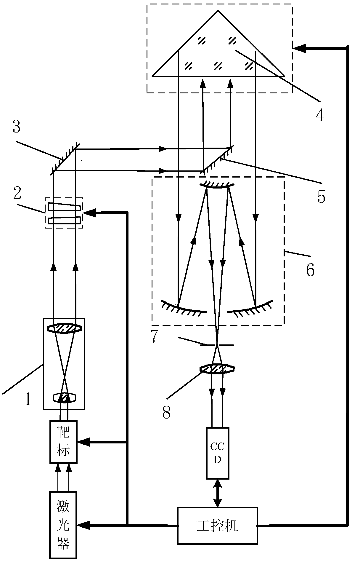
[0021] Such as figure 1 The laser radar coaxial detection system based on double wedges shown includes industrial computer, laser, beam expander 1, double wedge adjuster 2, 45° plane reflector 3, 45° plane reflective prism 4, corner reflector 5. Receiving telescope 6, aperture diaphragm 7, collimating mirror 8 and CCD camera. The laser emits a laser beam with a certain energy under the control of the industrial computer, first passes through the beam expander 1, the double wedge adjuster 2, the 45° plane reflector 3 and the 45° plane reflector 4, and then the beam reflected by the corner reflector 5 The signal is focused to the pinhole diaphragm 7 through the receiving telescope 6, and then received by the CCD camera after passing through the collimating mirror 8.

[0022] In the double-wedge-based lidar coaxial detection system of the presen...


PUM


Abstract

The invention discloses a laser radar coaxial detection system and an automatic calibration method therefor, and the system comprises an industrial control computer, a laser, a beam expanding lens (1), a double-optical-wedge adjuster (2), a 45-degree plane reflector (3), a 45-degree plane reflecting prism (4), a corner reflector (5), a receiving telescope (6), an aperture diaphragm (7), a collimating mirror (8), and a CCD camera. The laser is controlled by the industrial control computer to emit a laser beam with certain energy, and the laser beam sequentially passes through the beam expanding lens (1), the double-optical-wedge adjuster (2), the 45-degree plane reflector (3) and the 45-degree plane reflecting prism (4). A light beam signal reflected by the corner reflector (5) passes through the receiving telescope (6) to be focused on the aperture diaphragm (7), and then passes through the collimating mirror (8) to be received by the CCD camera. The system employs target calibration, and the signal is received by the CCD camera. A deflection angle value is calculated through a formula, and is fed back to a computer for controlling the double-optical-wedge adjuster (2) to carry out angle adjustment. The system is convenient, is not affected by an external environment, shields human errors through employing the digitalization technology, and can obtain higher precision.

Description

technical field [0001] The invention belongs to the technical field of laser radar, and specifically relates to a laser radar coaxial detection system and an automatic calibration method. The system analyzes the optical axis angle value received by a CCD, and controls the rotation angle of a double optical wedge regulator to achieve automatic calibration. the goal of. Background technique [0002] The laser radar system can monitor parameters such as atmospheric aerosol backscatter coefficient, atmospheric extinction coefficient, atmospheric particle mass concentration, and atmospheric boundary layer height in real time. With my country's emphasis on environmental pollution, laser radar is developing atmospheric science, atmospheric It plays an increasingly important role in the fields of climatology and atmospheric environmental science. At present, most laser radar systems adopt the coaxial method of transmitting and receiving devices, and the system mainly includes a tran...

Claims


Application Information

Patent Timeline
IPC IPC(8): G01S7/497
CPCG01S7/497
Inventor 郑朝阳张天舒刘洋刘吉瑞李春婷项衍周培松吕丽慧
Owner 皖江新兴产业技术发展中心
Learn More