

Greenhouse roller shutter control mechanism and method
A technology of control mechanism and shutter machine, applied in greenhouse cultivation, program control, computer control, etc., can solve the problems of inability to realize centralized management, large area management of agricultural greenhouses, and low degree of automation, so as to save personnel costs and improve automation degree, the effect of improving accuracy
- Summary
- Abstract
- Description
- Claims
- Application Information
AI Technical Summary
Problems solved by technology
Method used
Image

Examples
Embodiment 1
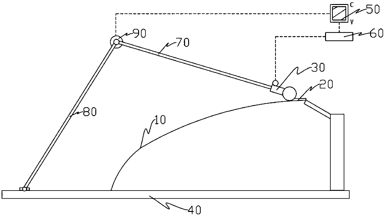
[0038] Such as figure 1 Shown is a structural schematic diagram of Embodiment 1 of a greenhouse roller shutter control mechanism, the roller shutter control mechanism includes a thermal insulation quilt 20 covered on the greenhouse film 10, a roller shutter machine 30 fixed on the reel of the thermal insulation quilt 20, and a hinge The support structure fixedly connected to the roller shutter machine 30 on the ground 40, the controller 50 for controlling the operation of the roller shutter machine, and the motor reversing mechanism 60 connected with the controller 50 to control the running direction of the roller shutter machine 30, the support structure includes one end The upper link 70 fixed on the shutter machine 30, one end is hinged to the upper link 70 and the other end is hinged to the lower link 80 on the ground, and the angle code fixed at the hinged connection between the upper link 70 and the lower link 80 90, the angle encoder 90 is connected to the controller 50...
Embodiment 2
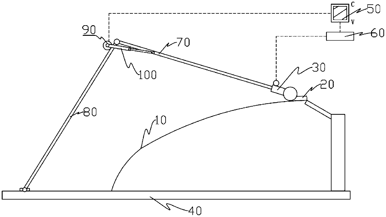
[0042] Embodiment two: if figure 1 Shown is a structural schematic diagram of Embodiment 2 of a greenhouse roller shutter control mechanism, the roller shutter control mechanism includes a thermal insulation quilt 20 covered on the greenhouse film 10, a roller shutter machine 30 fixed on the reel of the thermal insulation quilt 20, and a hinge The support structure fixedly connected with the roller shutter machine 30 on the ground 40, the controller 50 that controls the operation of the roller shutter machine 30, and the motor reversing mechanism 60 connected with the controller 50 to control the running direction of the roller shutter machine 30, the support structure includes One end is fixed on the upper link 70 on the roller blind machine 30, the lower link 80 hinged on the ground 40 is hinged with the upper link 70, and the telescopic link is hinged between the upper link 70 and the lower link 80 100 and an angle encoder 90 fixed at the hinge joint between the telescoping...
Embodiment 3
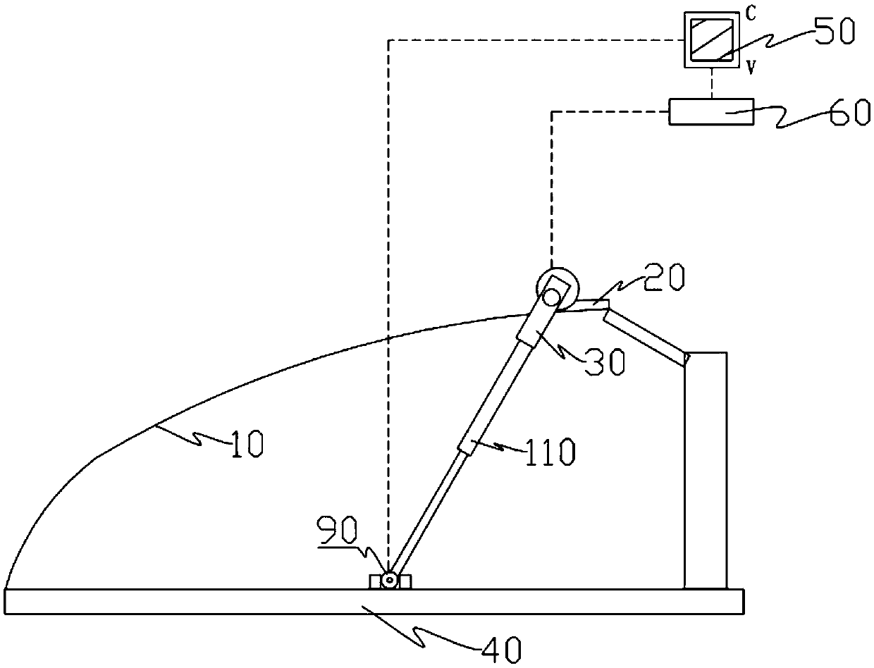
[0047] Such as image 3 Described is the third embodiment of a greenhouse roller blind control mechanism of the present invention, the greenhouse roller blind control mechanism includes a thermal insulation quilt 20 covered on the greenhouse film 10, a roller shutter machine 30 fixed on the thermal insulation quilt 20 reel , the support structure that the hinge is fixedly connected to the roller shutter machine 30 on the ground 40, the controller 50 that controls the operation of the roller shutter machine 30, and the motor reversing mechanism 60 connected with the controller 50 to control the running direction of the roller shutter machine 30, the support The structure includes a telescopic link 110 with one end fixed on the roller blind machine 30 and the other end hinged on the ground 40; the connection end between the telescopic link 110 and the ground 40 is fixed with an angle encoder 90, and the angle encoder 90 Signal connection with the controller 50.
[0048] The sta...
PUM
 Abstract
Description
Claims
Application Information