
Constant current source generation circuit

A technology for generating circuits and constant current sources, which is applied in the direction of adjusting electrical variables, control/regulation systems, instruments, etc., can solve the problems of small power supply range, component temperature drift interference, and limitations, so as to improve accuracy and load power , easy to control, and reduce the effect of current changes

Active Publication Date: 2018-05-18
SHANGHAI YIDIAN SCI INSTR
View PDF5 Cites 0 Cited by
  • Summary
  • Abstract
  • Description
  • Claims
  • Application Information

AI Technical Summary

Problems solved by technology

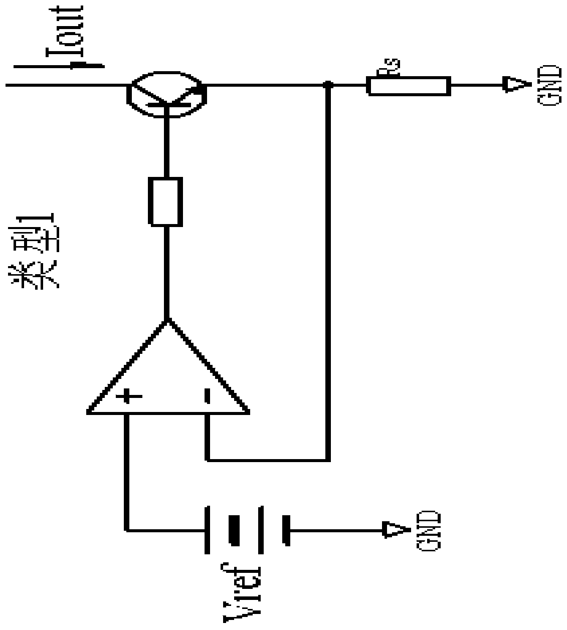
Less components are used and the structure is relatively simple, but the range of power utilization is small and the accuracy is relatively poor
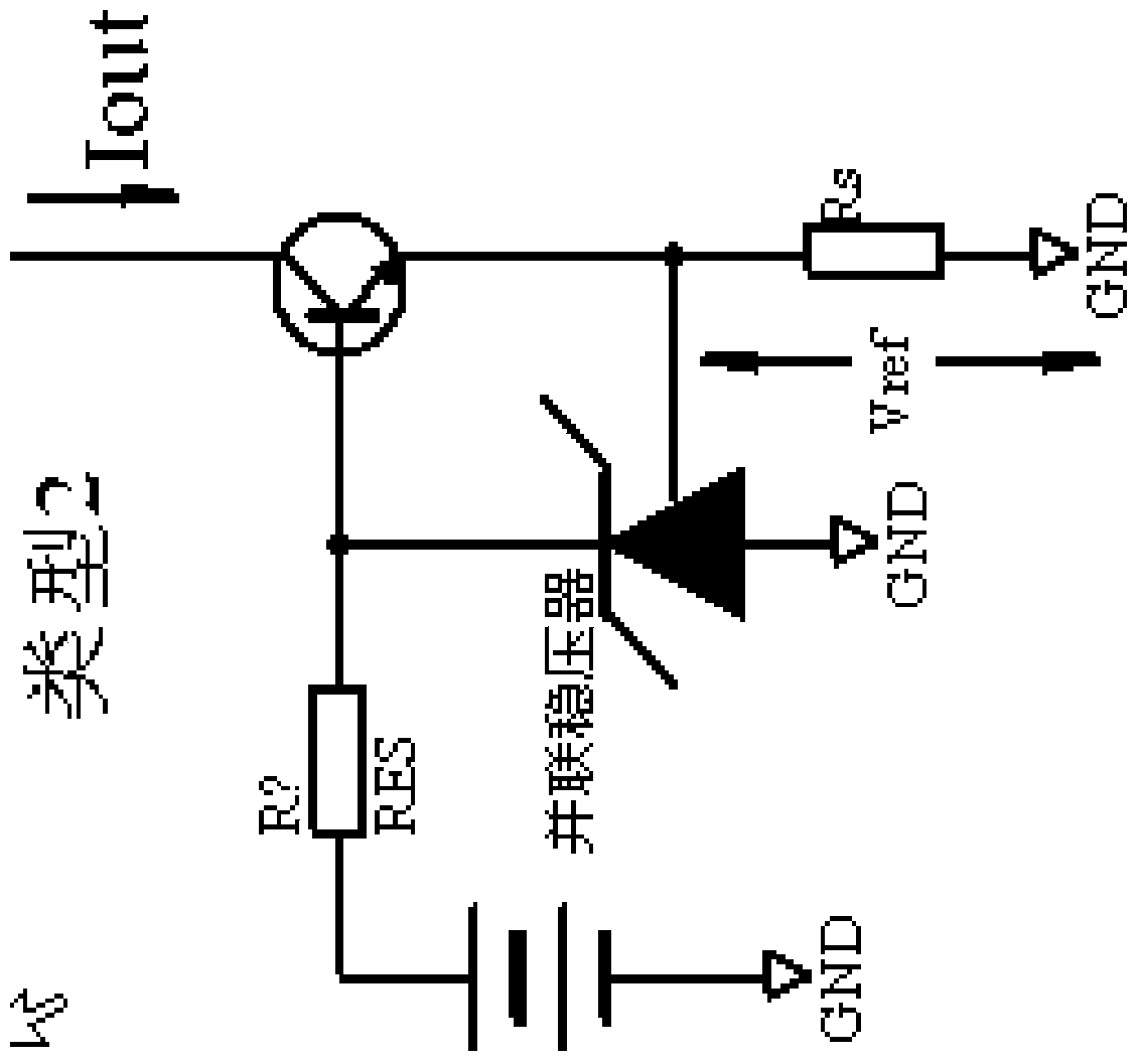
Or directly use the constant current source chip (as attached figure 2 As shown), such as XTR110KP, the accuracy is very high but there are still limitations, the power supply voltage cannot exceed 40V, the maximum current is 200mA and the temperature drift interference of components is very high

Method used


Image

  • Constant current source generation circuit
  • Constant current source generation circuit
  • Constant current source generation circuit

Examples


Embodiment Construction

[0027] The present invention will be further described below with reference to the drawings and embodiments.

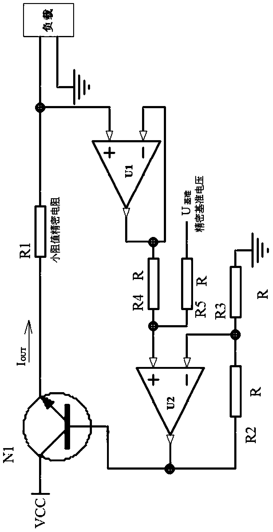
[0028] An embodiment of the present invention (as attached Figure 4 Shown) is to expand the constant current source circuit, with multiple currents of different sizes that can be switched. The precision reference voltage is divided by 4 potentiometers, and the electronic switch WS is switched on. According to the different potentials of the conduction, constant current sources of different sizes can be obtained, and the size is Iout=(U The reference voltage -0.7) / (R1).

[0029] In this example, a 5 volt reference voltage is used to load five potentiometers with a total value of 100 kilohms. The other ends are all grounded at the same time. The regulating ends are divided into 4 voltages of about 4.7 volts, 2.7 volts, 1.7 volts, Potentials below 0.9 volts and 0.7 volts are respectively switched by the electronic switch WS, model MAX4051, corresponding to 200mA, 100mA, 50m...


PUM


Abstract

The invention relates to a constant current source generation circuit, in particular to a constant current source generation circuit which is suitable for controlling current magnitude with direct current voltage, belonging to the technical field of an electronic circuit. The constant current source generation circuit comprises a sample amplifier U1, a summator U2, a triode N1, resistors R1, R2, R3, R4 and R5, a load and a power supply that are in circuit connection, wherein the sample amplifier U1 has sampling action for the power supply and is used for sampling the potential of the load, the summator U2 is an addition operation amplifier, the positive potential of the summator U2 is an intermediate value of the sample potential and the precise normal potential, and through two times of feedback amplification, the positive potential of the summator U2 is the sum of the sample potential and the precise normal potential; the output of the summator U2 is connected with a common base of the triode N1 to control the voltage output of the common base, the change the summator U2 is changed along with the change of the load sample, and then the voltage output is regulated by the triode N1 to reach potential balance. The constant current source generation circuit has the characteristics that the precision and the load power are improved, the circuit structure is simple, the cost is low, the control is easy, etc.

Description

Technical field [0001] The invention relates to the technical field of electronic circuits, in particular to a constant current source generating circuit suitable for controlling the magnitude of current with a direct current voltage. Background technique [0002] As we all know, the generation of constant current source is generally composed of power supply, constant current source and load. Use shunt regulator, op amp, transistor to form a simple constant current source circuit (as attached figure 1 Shown) to achieve a constant current. There are fewer components and the structure is simpler, but the power utilization range is smaller and the accuracy is relatively poor. Or directly use the constant current source chip (if attached figure 2 (Shown), such as XTR110KP, the accuracy is very high but there are still limitations, the power supply voltage cannot exceed 40V, the maximum current is 200mA, and the temperature drift interference of the components is very high. Summary...

Claims


Application Information

Patent Timeline
Patent Type & Authority Patents(China)
IPC IPC(8): G05F1/56
CPCG05F1/56
Inventor 宋翔鹰朱建波
Owner SHANGHAI YIDIAN SCI INSTR
Learn More