
A Four-band Microstrip Reflectarray Antenna

A technology of reflectarray antennas and reflectarrays, which is applied in the directions of antennas, antenna arrays, and individually powered antenna arrays, etc., can solve problems such as limited dual-band, and achieve the effects of easy engineering implementation, high engineering application value, and good quad-band radiation performance

Active Publication Date: 2018-11-13
NAT SPACE SCI CENT CAS
View PDF4 Cites 0 Cited by
  • Summary
  • Abstract
  • Description
  • Claims
  • Application Information

AI Technical Summary

Problems solved by technology

In the existing literature, most multi-bands are limited to dual-band, and there are few designs for tri-band and above

Method used


Image

  • A Four-band Microstrip Reflectarray Antenna
  • A Four-band Microstrip Reflectarray Antenna
  • A Four-band Microstrip Reflectarray Antenna

Examples


Embodiment Construction

[0033] The present invention will be further described now in conjunction with accompanying drawing.

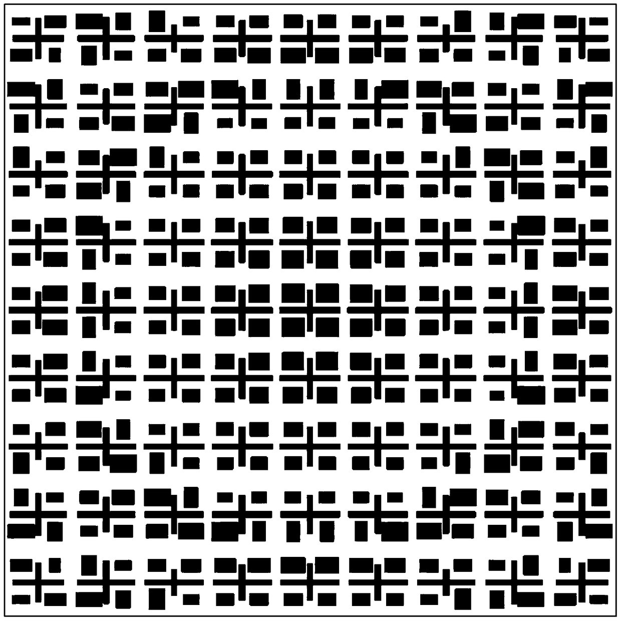
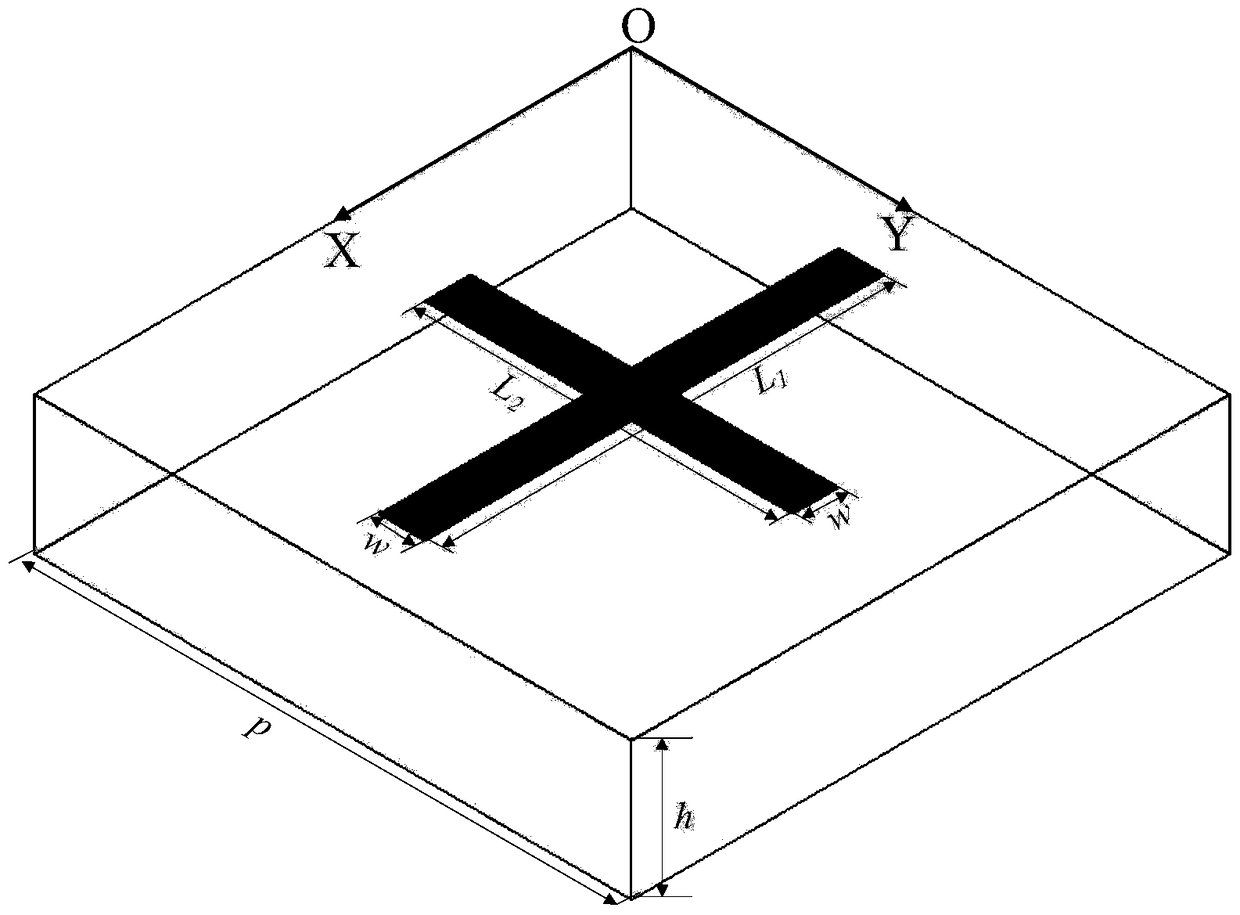
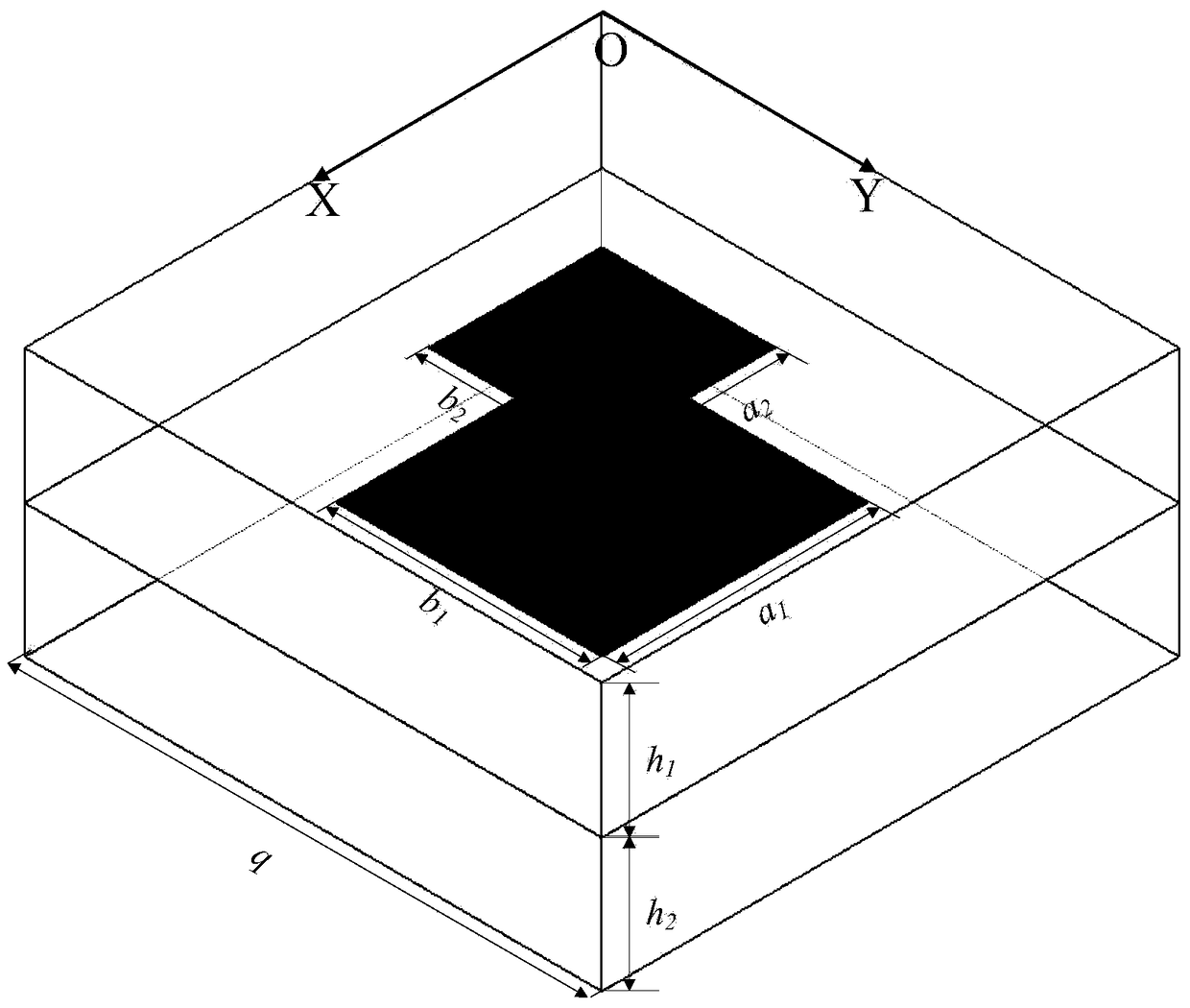
[0034] Such as Figure 8 As shown, a kind of four-band microstrip reflectarray antenna of the present invention comprises: a feed source and a microstrip reflectarray, the feed source is a pyramidal horn antenna, and the microstrip reflectarray includes a plurality of evenly arranged single-layer ten Zigzag vibrator unit and double-layer rectangular patch unit. Among them, a plurality of single-layer cross-shaped vibrator units are arranged in rows horizontally and vertically in columns; four double-layer rectangular patch units are distributed around each single-layer cross-shaped vibrator unit, and the center of the cross-shaped vibrator unit is opposite to it. The centers of four adjacent double-layer rectangular patch units have the same distance. The operating frequencies of the antenna are 9GHz, 13.58GHz, 24GHz and 30GHz respectively. The single-layer cross-shaped osc...


PUM


Abstract

The invention relates to a four-frequency microstrip reflective array antenna which comprises a feed source and a microstrip reflective array. The feed source is a pyramidal horn antenna. The microstrip reflective array comprises a plurality of uniformly arranged single-layer cross-shaped oscillator units and double-layer rectangular plaster units, wherein the plurality of single-layer cross-shaped oscillator units are arranged in lines in the transverse direction and are arranged in rows in the longitudinal direction. Four double-layer rectangular plaster units are distributed at the periphery of each single-layer cross-shaped oscillator unit. The distances between the center of each single-layer cross-shaped oscillator unit and the four adjacent double-layer rectangular plaster units are same. The working frequencies of the four-frequency microstrip reflective array antenna are 9GHz, 13.58GHz, 24GHz and 30GHz. The single-layer cross-shaped oscillator units operate in 9GHz and 13.58GHz through two directions which are crossed with each other. The double-layer rectangular plaster units operate in 24GHz and 30GHz through two directions which are crossed with each other.

Description

technical field [0001] The invention belongs to the technical field of antennas, in particular to a four-frequency microstrip reflective array antenna. Background technique [0002] Parabolic antennas and array antennas are widely used as traditional spaceborne antennas. Although the parabolic antenna has high gain and wide operating frequency range, it has the disadvantages of large size, heavy weight, difficult installation, and difficult processing, especially at high frequencies. Although the array antenna is small in size, flexible in scanning mode and wide in range, it has low efficiency, complex feeding network, large transmission loss, and expensive active devices loaded. These shortcomings limit the application of the above two antennas in radar, satellite communication, etc. to a certain extent. [0003] The microstrip reflectarray antenna is an antenna form that combines several advantages of the parabolic antenna and the array antenna. It is composed of a feed ...

Claims


Application Information

Patent Timeline
Patent Type & Authority Patents(China)
IPC IPC(8): H01Q21/06H01Q1/36
CPCH01Q1/36H01Q21/064
Inventor 薛飞王宏建易敏陈雪刘广
Owner NAT SPACE SCI CENT CAS
Learn More