A connector automatic crimping machine, crimping system and crimping process

A crimping machine and connector technology, applied in the direction of connection, fixed connection, line/collector components, etc., can solve the problems of PCB board damage, waste of time and labor, and affect crimping efficiency

Active Publication Date: 2018-12-14
SHENZHEN XING GRAIN AUTOMATION CO LTD
View PDF11 Cites 0 Cited by
  • Summary
  • Abstract
  • Description
  • Claims
  • Application Information

AI Technical Summary

Problems solved by technology

Connectors and PCB boards generally adopt the structure of pins and pinholes. The working principle of the crimping machine is to press the pins of the connector into the pinholes of the PCB board, so that the connector is connected to the PCB board; however, the actual production and manufacturing In the process, the crimping machine does not work alone, but is designed on the PCB board production line as a process in the PCB board production process. Therefore, the interaction between the transportation process of the PCB board and the crimping process of the crimping machine The connection and cooperation directly affect the crimping efficiency and crimping quality of the entire crimping machine; in addition, the connector and the PCB generally adopt a pin-to-pin hole matching structure. The installation accuracy is high. In the actual crimping process, due to factors such as assembly errors and displacement caused by vibration during the transmission process, the position of the indenter and the connector pins deviate, which may easily lead to damage to the connection during later crimping. In addition, in actual production and processing, the form and structure of connectors are ever-changing, with different application objects, frequencies, power, application environments, etc., there are various types of connectors, for different connector needs Setting multiple different crimping heads requires replacement of different crimping heads in the process of crimping different connectors. The replacement of multiple crimping heads wastes time and labor and affects crimping efficiency; in addition, in the actual crimping process, crimping When the head part is crimping the connector pins, the following situations will occur: 1. During the automatic working process of the crimping machine, the connector on the PCB board will be missed. At this time, if the crimping head continues to crimp the PCB board , then it is directly crimped on the PCB board, resulting in damage to the PCB board; 2. The pinhole on the PCB board is too large, or the pin diameter of the connector is too small, which will lead to unstable connection between the pin and the pinhole after crimping 3. Since it is an instant action for the crimping head to press the pin into the pinhole, the connection is made firm through the deformation of the pin. Therefore, the excessive deformation of the pin during the crimping process will cause the material layer of the pin to break and make the connection invalid. And after the crimping is completed, the pins have deformation and rebound, which also leads to connection failure; 4. During the crimping process of the connector, there will be kneeling pins. After kneeling, the pins are bent and broken, and cannot be inserted into the pinholes. If the crimping head continues to crimp downward, it will be directly pressed to the PCB board, resulting in damage to the PCB board; 5. During the replacement of the indenter parts, there is a missing installation, resulting in the crimping assembly not being installed with the indenter parts; 6. In actual work, there may be abnormal conditions in the stroke of the indenter moving down from the Z-axis zero point to the connector and the motion stroke inserted into the connector, and it is necessary to stop the movement in time; 7. In addition, during the crimping process, the crimping Stroke control is based on the detected PCB board thickness and measured liner thickness as theoretical data. The actual PCB board thickness detection and liner installation errors will lead to too large or too small crimping according to the theoretical data, resulting in PCB board crushing Or the crimping is not in place

Method used


Image

  • A connector automatic crimping machine, crimping system and crimping process
  • A connector automatic crimping machine, crimping system and crimping process
  • A connector automatic crimping machine, crimping system and crimping process

Examples


Embodiment 1

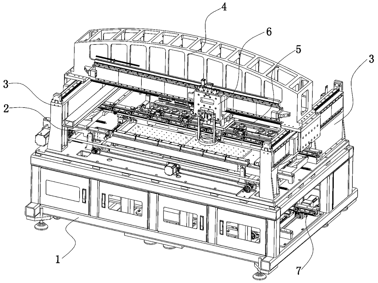
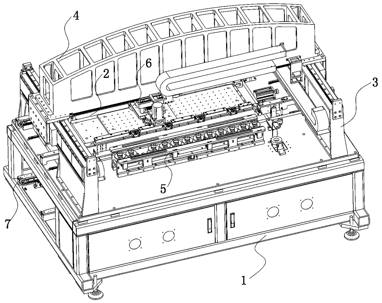
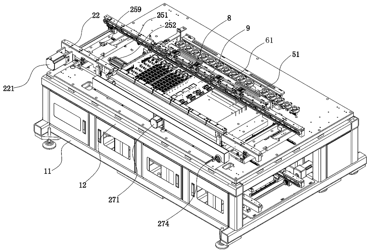
[0091] Example 1: Such as figure 1 As shown in Figures to 18, the technical solution adopted by the present invention is as follows: an automatic connector crimping machine, including a body 1, a gantry support guide assembly, a guide assembly 2, a crimping joint replacement assembly 5, and a crimping assembly 6, Wherein, the body 1 is an upper and lower layer structure, and the guide assembly 2 is arranged in the upper space of the body 1; the gantry support and guide assembly is fixed on the upper part of the body 1, and the gantry support and guide assembly is covered with an outer cover to form an overall crimping machine structure The above-mentioned material guide assembly 2 passes through the left and right sides of the crimping machine, and the PCB board with the connector is introduced into the crimping machine, and the PCB board is limited and fixed under the gantry support guide assembly; the above-mentioned crimping joint replacement assembly 5 is arranged on the sid...

Embodiment 2

[0112] Example 2: Such as Picture 20 , 21 , 26, 27, 28, 29, a crimping process of a connector automatic crimping machine, the crimping process has a Z-axis zero point, a crimping zero point O1 and a theoretical zero point O2, where the Z-axis zero point is the pressure The starting point of the downward movement of the head part 61 in the vertical direction, the height of the crimping zero point O1 is flush with the gasket surface, and the theoretical zero point O2 is the crimping zero point O1 minus the thickness of the PCB board, the thickness of the connector bottom shell and the connector The value after the height of the pin crimping step surface; the movement stroke of the indenter 61 through the Z-axis zero point downward crimping process includes no-load stroke, insertion stroke a and crimping stroke b, among which the no-load stroke is the Z-axis zero point The distance between the top surface of the connector, the insertion stroke a is the distance from the top surfac...

Embodiment 3

[0121] Example 3: Such as Picture 20 , 21 , 30, 31, 32, 33, a crimping process of a connector automatic crimping machine, the crimping process has a Z-axis zero point, a crimping zero point O1 and a theoretical zero point O2, where the Z-axis zero point is the pressure The starting point of the downward movement of the head part 61 in the vertical direction, the height of the crimping zero point O1 is flush with the gasket surface, and the theoretical zero point O2 is the crimping zero point O1 minus the thickness of the PCB board, the thickness of the connector bottom shell and the connector The value after the height of the pin crimping step surface; the movement stroke of the indenter 61 through the Z-axis zero point downward crimping process includes no-load stroke, insertion stroke a and crimping stroke b, among which the no-load stroke is the Z-axis zero point The distance between the top surface of the connector, the insertion stroke a is the distance from the top surfac...


PUM


Abstract

The invention discloses an automatic press-connection machine of a connector and a press-connection system and press-connection process thereof. The automatic press-connection machine comprises a machine body, a portal frame supporting and guiding assembly, a material guiding assembly, a press-connection head replacing assembly and a press-connection assembly; the press-connection system comprises an IPC control chip, a height sensor connected with the IPC control chip, a CCD module, a movement control card, a linear motor and a data acquisition card; the press-connection process comprises a PARS press-connection module, a pressure press-connection module and a distance press-connection module. The automatic press-connection machine of the connector and the press-connection system and press-connection process thereof are applicable to a modern assembly line, fully-automatic material guiding control is adopted, a plurality of press-connection head components are arranged therein, multiple types of press-connection modes are correspondingly matched with the press-connection head components, in the press-connection process, pres-connection heads are replaced automatically, and product press-connection diversity is achieved.

Description

Technical field [0001] The invention relates to the field of automatic machinery, in particular to a connector automatic crimping machine, a crimping system and a crimping process thereof. Background technique [0002] Connectors, namely CONNECTOR, also known as connectors, plugs and sockets. Connectors connect conductors / wires with appropriate mating components to realize circuit connection and disconnection. It is a common circuit component; the connector is in the circuit Between the blocked or isolated circuits, bridges of communication are built to allow current to flow and the circuit to achieve predetermined functions. Connectors are indispensable components in electronic equipment. One or more connectors. Connectors and PCB boards generally adopt a pin and pin hole matching structure. The working principle of the crimping machine is to press the pins of the connector into the pin holes of the PCB board to connect the connector to the PCB board; however, actual manufactur...

Claims


Application Information

Patent Timeline
Patent Type & Authority Patents(China)
IPC IPC(8): H01R43/00H01R12/51
CPCH01R12/51H01R43/00
Inventor 宾兴
Owner SHENZHEN XING GRAIN AUTOMATION CO LTD
Why Eureka
Try Eureka