
Permanent magnet, permanent magnet motor and compressor

A technology of permanent magnet motors and permanent magnets, which is applied in the fields of permanent magnet motors, compressors, and permanent magnets. It can solve problems such as low manufacturing efficiency and complicated rotor assembly, and achieve the effects of saving material costs, improving cost performance, and improving performance.

Inactive Publication Date: 2016-04-20
GUANGDONG MEIZHI COMPRESSOR +1
View PDF6 Cites 11 Cited by
  • Summary
  • Abstract
  • Description
  • Claims
  • Application Information

AI Technical Summary

Problems solved by technology

However, this technology will bring manufacturing problems such as complicated rotor assembly and low manufacturing efficiency.

Method used


Image

  • Permanent magnet, permanent magnet motor and compressor
  • Permanent magnet, permanent magnet motor and compressor
  • Permanent magnet, permanent magnet motor and compressor

Examples


Embodiment Construction

[0031] Embodiments of the invention are described in detail below, examples of which are illustrated in the accompanying drawings. The embodiments described below by referring to the figures are exemplary and are intended to explain the present invention and should not be construed as limiting the present invention.

[0032] In describing the present invention, it should be understood that the terms "center", "longitudinal", "transverse", "length", "width", "thickness", "upper", "lower", "front", " Back", "Left", "Right", "Vertical", "Horizontal", "Top", "Bottom", "Inner", "Outer", "Clockwise", "Counterclockwise", "Axial", The orientation or positional relationship indicated by "radial", "circumferential", etc. is based on the orientation or positional relationship shown in the drawings, and is only for the convenience of describing the present invention and simplifying the description, rather than indicating or implying the referred device or element Must be in a particular ...


PUM


Abstract

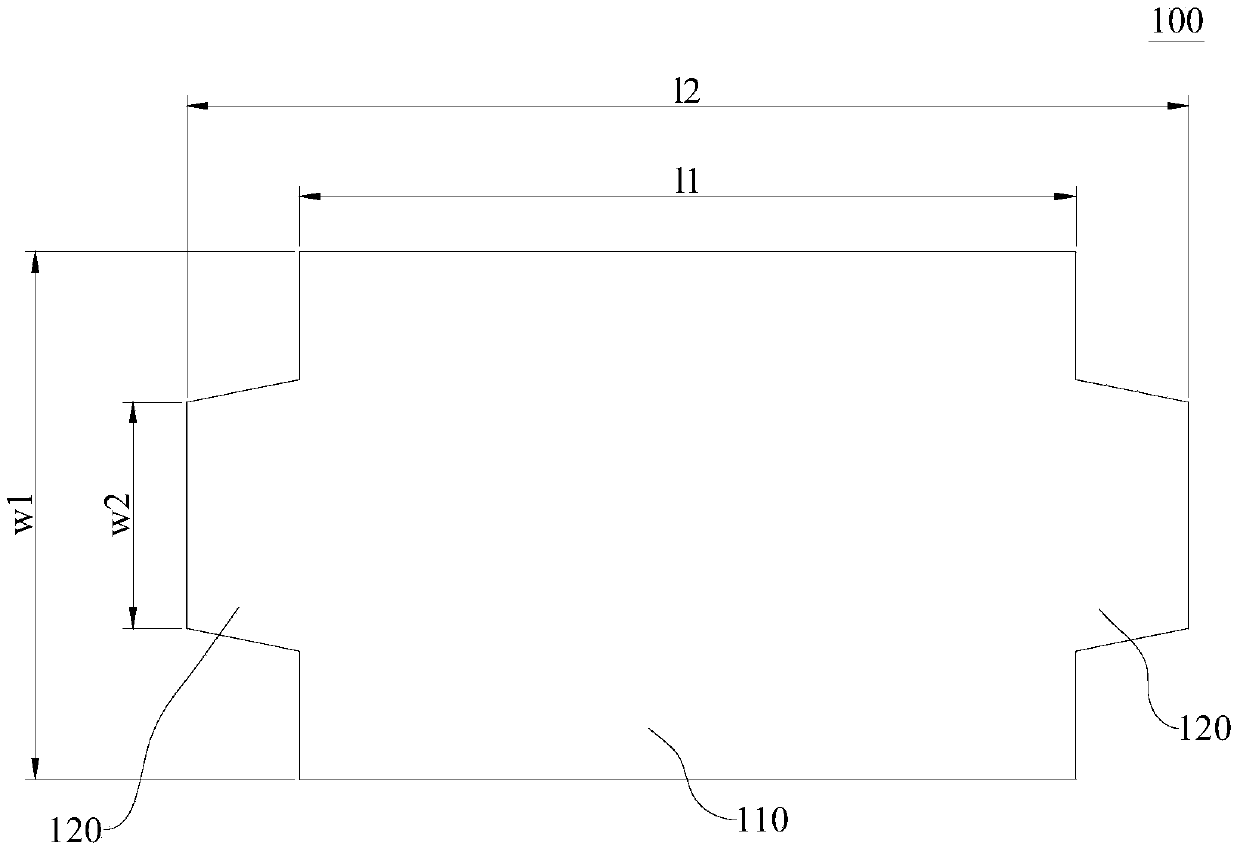
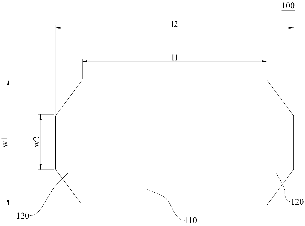
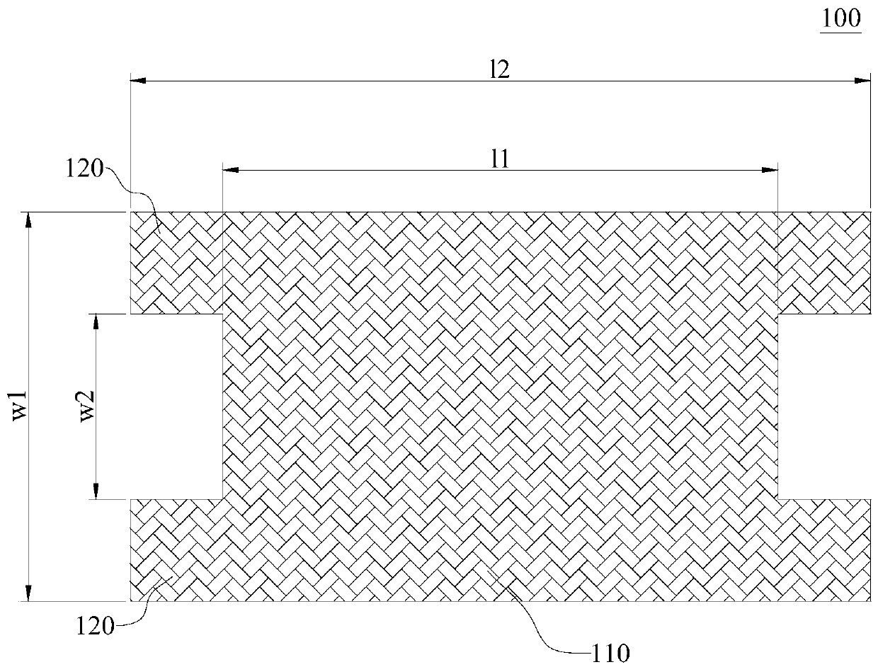
The invention discloses a permanent magnet, a permanent magnet motor and a compressor. The permanent magnet has the maximum length L1 and the maximum width W1. The working area of the permanent magnet is S, wherein the working area S, the maximum length L1 and the maximum width W1 meet the relational expression that S is smaller than L1*W1. According to the permanent magnet, the performance of the motor can be improved, the material cost can be saved, the rotor assembling difficulty of a rotor will not be increased, and therefore the cost performance of the motor is improved.

Description

technical field [0001] The invention relates to the field of refrigeration equipment, in particular to a permanent magnet, a permanent magnet motor and a compressor. Background technique [0002] In the compressor industry, the stator, rotor and permanent magnets of permanent magnet motors are generally arranged equal in axial length. Due to end effects such as end magnetic flux leakage, the utilization rate of the magnetic flux at the end of the motor is low, so the cost performance of the motor is low. As one of the solutions, setting the axial length of the permanent magnet to be smaller than the axial length of the rotor core can improve the utilization rate of the magnetic flux at the end to a certain extent and improve the cost performance of the motor. However, this technology will bring manufacturing problems such as complicated rotor assembly and low manufacturing efficiency. Contents of the invention [0003] The present invention aims to solve one of the techn...

Claims


Application Information

Patent Timeline
IPC IPC(8): H02K1/06
CPCH02K1/06H02K2213/03
Inventor 毛临书乔正忠于明湖
Owner GUANGDONG MEIZHI COMPRESSOR
Learn More