A spindle sealing method for a working motor under high temperature or high pressure environment

A high-voltage environment, working motor technology, applied in the direction of engine sealing, electromechanical devices, electrical components, etc., can solve the problems of easy damage to the seal, the motor cannot work normally and stably, and the motor is damaged.

Active Publication Date: 2018-10-09
DONGFANG ELECTRIC MACHINERY
View PDF5 Cites 0 Cited by
  • Summary
  • Abstract
  • Description
  • Claims
  • Application Information

AI Technical Summary

Problems solved by technology

[0004] The integrated submersible motor with a sealing device disclosed in this patent document is equipped with a sealing head on the upper end of the motor, directly connects with the submersible pump through the sealing head, and assembles a mechanical seal on the sealing head to meet the sealing requirements of the submersible motor. A single mechanical seal is easily damaged under the action of high temperature, high pressure and external multi-phase mixed liquid, resulting in the leakage of thin oil inside the motor, and at the same time, the external multi-phase liquid enters the inside of the motor and damages the motor, resulting in abnormal stability of the motor Work

Method used


Image

  • A spindle sealing method for a working motor under high temperature or high pressure environment
  • A spindle sealing method for a working motor under high temperature or high pressure environment
  • A spindle sealing method for a working motor under high temperature or high pressure environment

Examples


Embodiment 1

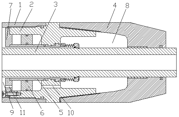
[0044] see figure 1 , a method for sealing a main shaft of a motor working in a high-temperature or high-pressure environment, comprising a packaging step, including a piston assembling step and a sealing step before the packaging step;

[0045] The piston assembling step refers to first assembling the piston rod 5 and the piston 6 between the motor housing 1 and the main shaft 3, and packaging the piston end cover 7;

[0046] The sealing step refers to assembling a first seal on the first joint 2, and assembling a second seal between the second joint 4 and the main shaft;

[0047] The packaging step refers to connecting the first joint 2 to the motor housing 1, the second joint 4 to the first joint 2, the first joint 2, the second joint 4 and the main shaft 3 to form a transition cavity 8, the motor housing 1, the main shaft 3 and the piston end cover 7 form an inner cavity 9, a first pressure balance hole 10 is set on the first joint 2, a second pressure balance hole 11 is ...

Embodiment 2

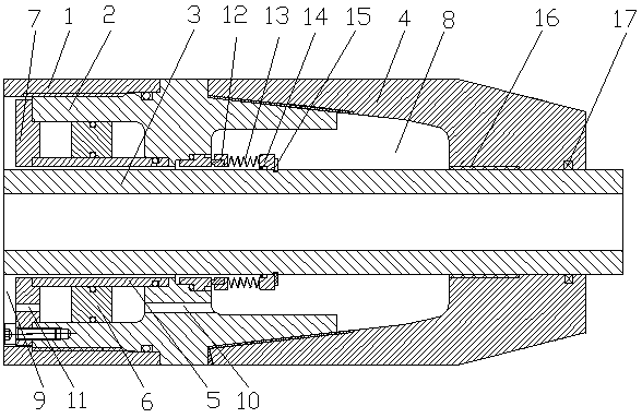
[0050] see figure 2 , a method for sealing a main shaft of a motor working in a high-temperature or high-pressure environment, comprising a packaging step, including a piston assembling step and a sealing step before the packaging step;

[0051] The piston assembling step refers to first assembling the piston rod 5 and the piston 6 between the motor housing 1 and the main shaft 3, and packaging the piston end cover 7;

[0052] The sealing step refers to assembling a first seal on the first joint 2, and assembling a second seal between the second joint 4 and the main shaft;

[0053] The packaging step refers to connecting the first joint 2 to the motor housing 1, the second joint 4 to the first joint 2, the first joint 2, the second joint 4 and the main shaft 3 to form a transition cavity 8, the motor housing 1, the main shaft 3 and the piston end cover 7 form an inner cavity 9, a first pressure balance hole 10 is set on the first joint 2, a second pressure balance hole 11 is...

Embodiment 3

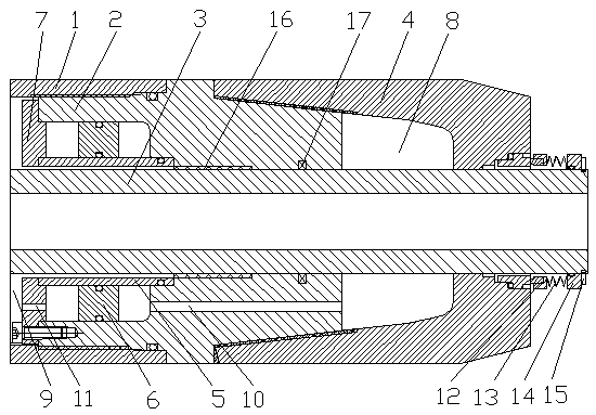
[0057] see image 3 , a method for sealing a main shaft of a motor working in a high-temperature or high-pressure environment, comprising a packaging step, including a piston assembling step and a sealing step before the packaging step;

[0058] The piston assembling step refers to first assembling the piston rod 5 and the piston 6 between the motor housing 1 and the main shaft 3, and packaging the piston end cover 7;

[0059] The sealing step refers to assembling a first seal on the first joint 2, and assembling a second seal between the second joint 4 and the main shaft;

[0060] The packaging step refers to connecting the first joint 2 to the motor housing 1, the second joint 4 to the first joint 2, the first joint 2, the second joint 4 and the main shaft 3 to form a transition cavity 8, the motor housing 1, the main shaft 3 and the piston end cover 7 form an inner cavity 9, a first pressure balance hole 10 is set on the first joint 2, a second pressure balance hole 11 is ...


PUM


Abstract

The invention discloses a spindle sealing method for a motor working under a high-temperature or high-pressure environment, which belongs to the technical field of motor equipment. The spindle sealing method is characterized in that a piston rod and a piston are first fitted between a motor housing and a spindle, and a piston end cover is fitted; a first sealing element is fitted on a first connector, and a second sealing element is fitted between a second connector and the spindle; the first connector is connected with the motor housing, the second connector is connected with the first connector, a transitional cavity is formed by the first connector, the second connector and the spindle, an internal cavity is formed by the motor housing, the spindle and the piston end cover, a first pressure balance hole is formed in the first connector, a second pressure balance hole is formed in the piston end cover, and the pressure balance between the transitional cavity and the internal cavity is regulated by means of the motion of the piston. Double sealing is adopted by the invention, the stable operation of the motor can be effectively ensured by the piston balancing the pressure difference between sealing, and the sealing method is simple and reliable.

Description

technical field [0001] The invention relates to the technical field of motor equipment, in particular to a method for sealing the main shaft of a working motor in a high-temperature or high-pressure environment. Background technique [0002] High temperature or high pressure environment refers to a pure high temperature or high pressure environment, or an environment with both high temperature and high pressure, such as the working environment of downhole motors, deep sea motors and other motors. Motors working in high-temperature or high-pressure environments not only have to withstand the effects of external high temperature and high pressure, but also the influence of external media on the motor cannot be ignored. Under normal conditions, the medium outside this type of motor is a multiphase mixed liquid, including solid phase, liquid phase and gas phase. The internal medium of the motor is usually a thin oil medium. Therefore, how to prevent the external medium at the r...

Claims


Application Information

Patent Timeline
Patent Type & Authority Patents(China)
IPC IPC(8): H02K5/124H02K5/10F16J15/16
CPCF16J15/164H02K5/10H02K5/124H02K2213/09
Inventor 孙立宾林坤李少斌李彬
Owner DONGFANG ELECTRIC MACHINERY
Why Eureka
Try Eureka