
Near-threshold-voltage automatic starting circuit applied to Boost converter

A threshold voltage and self-starting technology, which is applied in the direction of output power conversion devices and electrical components, can solve the problems of reducing the starting voltage of Boost circuits and increasing costs, and achieve the effect of shortening the starting time

Active Publication Date: 2016-04-20
XIDIAN UNIV
View PDF2 Cites 3 Cited by
  • Summary
  • Abstract
  • Description
  • Claims
  • Application Information

AI Technical Summary

Problems solved by technology

However, since the output of energy sensors can generally be as low as hundreds of millivolts or even tens of millivolts, traditional Boost circuits generally cannot start at such a low power supply voltage.
In order to reduce the start-up voltage of the Boost circuit, a low-threshold MOS tube is generally used to start the entire circuit, but this increases the cost

Method used


Image

  • Near-threshold-voltage automatic starting circuit applied to Boost converter
  • Near-threshold-voltage automatic starting circuit applied to Boost converter
  • Near-threshold-voltage automatic starting circuit applied to Boost converter

Examples


Embodiment Construction

[0037] Specific embodiments of the present invention will be described in detail below.

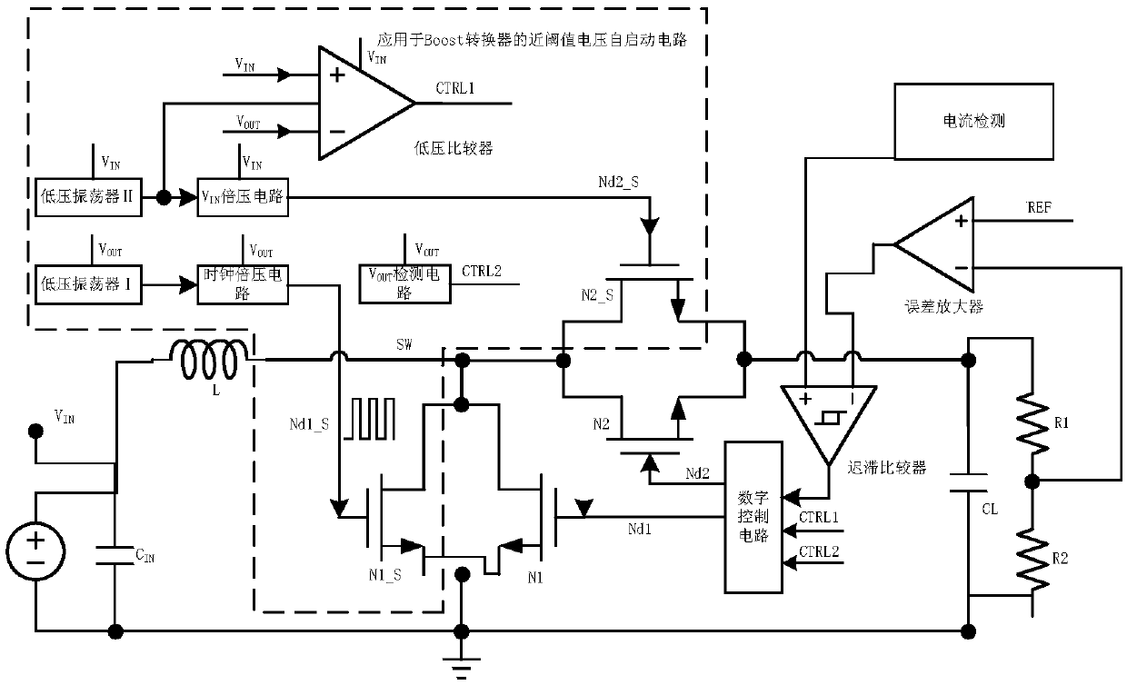
[0038] Such as figure 1 shown, the input voltage V IN One end of the ground, the input voltage V IN The other end of the capacitor is connected to one end of the inductor L, and the capacitor C IN One end of the ground, the capacitor C IN The other end is connected to one end of the inductor L, and one end of the inductor L is connected to the input voltage V IN Connected, the other end of the inductor L is connected to the drain of the auxiliary start transistor N1_S,

[0039] The low-voltage oscillator I is powered by the output, and the output terminal of the low-voltage oscillator I is connected to the input terminal of the clock voltage doubler circuit;

[0040] The low-voltage oscillator II is powered by the output, the output of the low-voltage oscillator II and the V IN The input terminal of the voltage doubler circuit is connected with the clock input terminal of the low vo...


PUM


Abstract

The invention relates to a near-threshold-voltage automatic starting circuit applied to a Boost converter. The near-threshold-voltage automatic starting circuit applied to the Boost converter comprises a low-voltage oscillator I, a low-voltage oscillator II, a VIN voltage doubling circuit, a low-voltage comparator, a VOUT detection circuit, a clock voltage doubling circuit, an auxiliary starting tube N1_S and an auxiliary starting tube N2_S. The output end of the low-voltage oscillator I is connected with the input end of the clock voltage doubling circuit. The output end of the low-voltage oscillator II is connected with the input end of the VIN voltage doubling circuit and the input end of the low-voltage comparator. The input end of the clock voltage doubling circuit is connected with the output end of the low-voltage oscillator I, and the output end of the clock voltage doubling circuit is connected to a grid electrode of the auxiliary starting tube N1_S. The input end of the VIN voltage doubling circuit is connected to the output end of the low-voltage oscillator II, and the output end of the VIN voltage doubling circuit is connected to a grid electrode of the auxiliary starting tube N2_S.

Description

technical field [0001] The invention relates to the field of integrated circuits, in particular to a near-threshold voltage self-starting circuit applied to a Boost converter. Background technique [0002] In the energy harvesting circuit, the Boost converter generally stabilizes the output voltage of the energy sensor to provide a stable DC voltage for the subsequent circuit. However, since the output of the energy sensor can generally be as low as hundreds of millivolts or even tens of millivolts, traditional Boost circuits generally cannot be started at such a low power supply voltage. In order to reduce the start-up voltage of the Boost circuit, generally a low-threshold MOS tube is used to start the whole circuit, but this increases the cost. Therefore, for the energy harvesting circuit, it is of great significance to design a low-cost, near-threshold self-starting circuit to reduce the starting voltage of the entire Boost converter. The invention provides a near-thre...

Claims


Application Information

Patent Timeline
IPC IPC(8): H02M1/36
CPCH02M1/36
Inventor 刘帘曦沐俊超张雪军朱樟明杨银堂
Owner XIDIAN UNIV
Learn More