Automatic workpiece welding state monitoring method

A welding state, automatic monitoring technology, applied in welding equipment, auxiliary welding equipment, welding/cutting auxiliary equipment, etc., can solve the problems of difficult welding seam length, affecting welding quality, low welding strength, etc., and achieve high practical value and accuracy. Monitoring, the effect of low investment cost

Inactive Publication Date: 2016-04-27
XIAN YUEFU ELECTRICAL TECH
View PDF0 Cites 7 Cited by
  • Summary
  • Abstract
  • Description
  • Claims
  • Application Information

AI Technical Summary

Problems solved by technology

[0003] When actually using an electric welding machine for welding processing, due to the high temperature of the welding position, it is difficult to grasp the length of the weld. There is a large error
Especially for welding processes with complex structures and precise welding quality requirements, it is often necessary to use different welding parameters (such as welding temperature, welding time, etc.) at different welding positions, so technicians need to accurately understand the current Welding status, including welding position, welding time, welding temperature, etc., so that the welding can be completed at one time. Otherwise, multiple repair weldings are required, which is not only time-consuming and laborious, but also has low welding efficiency and affects welding quality. The welding strength is low
In addition, for the purpose of protecting the eyes of the operator during the welding process, it is usually necessary to use a welding mask, which further increases the difficulty of accurately grasping the current welding status
In summary, there is a lack of a method with simple steps, reasonable design, high degree of intelligence, convenient implementation, and good use effect for automatic monitoring of workpiece welding status. During the welding process, the welding status at each moment can be automatically, real-time and accurately monitored monitor

Method used


Image

  • Automatic workpiece welding state monitoring method
  • Automatic workpiece welding state monitoring method

Examples


Embodiment Construction

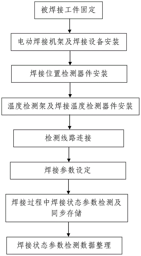
[0036] Such as figure 1 A method for automatically monitoring the welding state of workpieces shown includes the following steps:

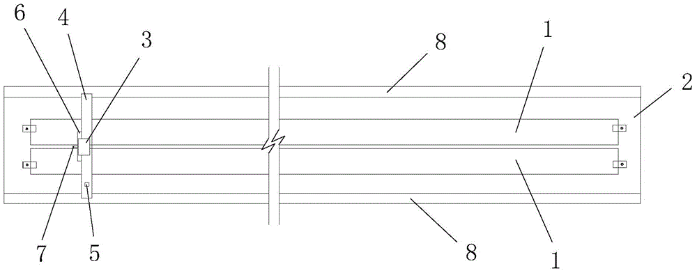
[0037] Step 1. Fix the workpiece to be welded: Fix the two workpieces 1 to be welded on the welding platform 2. For details, see figure 2 .

[0038] Step 2. Installation of electric welding frame and welding equipment: First, on the welding platform 2 described in step 1, install an electric welding machine that drives the welding equipment 3 to move from front to back along the welding area between the two workpieces 1 to be welded. frame 4, and then the welding equipment 3 is installed on the electric welding frame 4; the electric welding frame 4 is controlled by the welding controller and connected to the welding controller.

[0039] Step 3, installation of welding position detection device: install a position detection unit 5 for real-time detection of its moving position on the electric welding frame 4 installed in step 2.

[0040] Step 4...


PUM


Abstract

The invention discloses an automatic workpiece welding state monitoring method which comprises the following steps that Step one, a to-be-welded workpiece is fixed; Step two, an electric welding rack and welding equipment are mounted; Step three, a welding position detector is mounted; Step four, a temperature detection rack and a welding temperature detector are mounted; Step five, detection lines are connected; Step six, welding parameters are set; Step seven, welding state parameters in a welding process are detected and stored synchronously; and Step eight, welding state parameter detection data are sorted: in the welding process, a data processor calls a welding path making module to make a welding path curve of the welding equipment, calls a welding position change module to make a welding-time-dependent welding position change curve of the welding equipment, and calls a tabulation module to make a welding state parameter list. The method is simple in step, reasonable in design, high in intelligence degree, convenient to realize and good in using effect, and can automatically and precisely monitor welding states of each moment in real time in the welding process.

Description

technical field [0001] The invention relates to a monitoring method, in particular to an automatic monitoring method for workpiece welding status. Background technique [0002] Welding is a processing method that uses heat, pressure, or a combination of heat and pressure, and with or without filler materials, to achieve atomic bonding of welded parts, and welding is a method of connecting separate M metal parts into a non-detachable A method of machining a solid metal part. At present, welding technology has been widely used in daily industrial production. At the same time, there are more and more types of welding equipment appearing on the market, and the working performance of welding equipment has also been greatly improved. [0003] When actually using an electric welding machine for welding processing, due to the high temperature of the welding position, it is difficult to grasp the length of the weld. There are large errors. Especially for welding processes with com...

Claims


Application Information

Patent Timeline
Patent Type & Authority Applications(China)
IPC IPC(8): B23K37/00
Inventor 汪晓峰
Owner XIAN YUEFU ELECTRICAL TECH
Why Eureka
Try Eureka