Eureka AIR delivers breakthrough ideas for toughest innovation challenges, trusted by R&D personnel around the world.

Synthetic thermal jet exciter for removing damp/frost/ice and application thereof

A technology for synthesizing jets and exciters, which is applied in the field of jets, can solve the problems that clothes are not easy to dry, tents and sleeping bags are wet and cold, and shoes and socks are wet, etc., and achieve the effects of accelerating heat transport and diffusion, simple and lightweight structure, and simple and lightweight structure.

Active Publication Date: 2016-04-27
NAT UNIV OF DEFENSE TECH
View PDF6 Cites 7 Cited by
  • Summary
  • Abstract
  • Description
  • Claims
  • Application Information

AI Technical Summary

Problems solved by technology

The defrosting process needs to warm up the car first, wait for the engine water temperature to rise, and then turn on the heater to defrost, which is time-consuming, labor-intensive and fuel-intensive
In rainy and snowy weather, water droplets and mist are easy to adhere to the rearview mirror, which seriously affects driving safety. At present, the back of the glass is generally heated by an electric heater to defog and evaporate water droplets, which is very time-consuming and power-consuming.
[0004] In daily life, travel and outdoor sports, there are common problems of dehumidification, defrosting and deicing. For example, frost and ice in the refrigerator cause the refrigeration effect of the refrigerator to decline; in winter and spring, especially in the south where there is much rain and the climate is cold and humid, cleaning The clothes are not easy to dry, and the shoes and socks are wet; during travel and outdoor sports, we often have such problems: clothes, shoes and socks cannot be dried in time, tents and sleeping bags are wet and cold, etc.

Method used


Image

  • Synthetic thermal jet exciter for removing damp/frost/ice and application thereof
  • Synthetic thermal jet exciter for removing damp/frost/ice and application thereof
  • Synthetic thermal jet exciter for removing damp/frost/ice and application thereof

Examples


Embodiment Construction

[0023] Below, the present invention will be further described in conjunction with the accompanying drawings and specific embodiments.

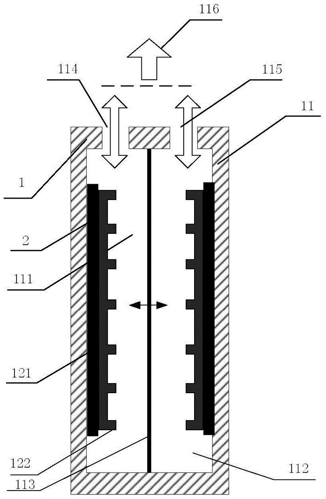
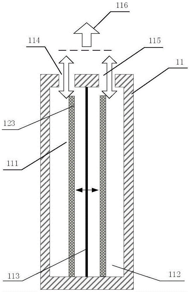
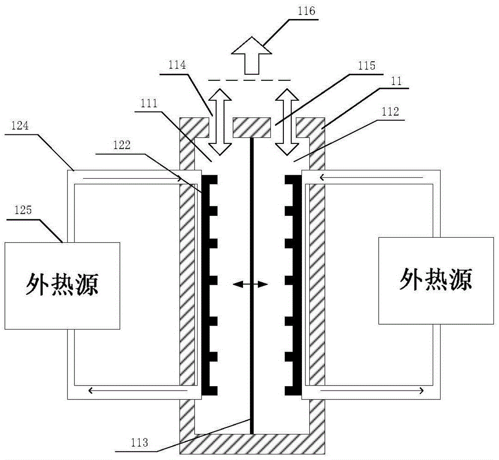
[0024] Such as figure 1 As shown, it is a schematic structural diagram of a synthetic thermal jet actuator whose heat source is an electric heater in the present invention; it is composed of a synthetic jet actuator 11 and a heat source 12; the synthetic jet actuator is composed of a cavity, a vibrating membrane and an outlet, and the cavity One or more outlets are opened; the heat source is arranged inside the cavity. figure 1 Among them, the synthetic jet actuator is a single-membrane double-cavity synthetic jet actuator, and its specific structure includes a first cavity 111, a second cavity 112, a vibrating membrane 113, and a gap between the first cavity 111 and the second cavity 112. Separated by the vibrating membrane, the first cavity 111 corresponds to a first cavity outlet 114 , and the second cavity 112 corresponds to a second cavi...


PUM


Abstract

The invention belongs to the field of jet technology and relates to a synthetic thermal jet exciter for removing damp / frost / ice and application thereof. The synthetic thermal jet exciter is composed of synthetic jet exciters and heat sources, wherein each synthetic jet exciter is composed of a cavity, a vibration diaphragm and an outlet, the cavity is provided with one or more of outlets, and the heat source is arranged in the cavity. The synthetic thermal jet exciter can be singly used and also can be installed in the equipment needing to be heated to form an array to be used, a heating device is additionally arranged in an existing exciter cavity, and a thermal jet with a relatively high speed is synthesized at each outlet so as to be used for removing damp, frost and ice. The synthetic thermal jet exciter has the advantages of no need for gas sources, simple and portable structure, rapid response, high efficiency, low energy consumption and the like, can be used for small and medium-sized aircrafts, vehicles, refrigerators and the like for removing ice and frost, and also can be used for hand dryers, clothes dryers, shoe dryers and the like for removing damp.

Description

technical field [0001] The invention belongs to the technical field of jet flow, and in particular relates to a synthetic thermal jet actuator for dehumidification / frost / ice and its application. Background technique [0002] Icing is a phenomenon that widely exists in aircraft flight, and it is also one of the main hidden dangers that cause flight safety accidents. When the aircraft is flying under icing weather conditions below the freezing point, the supercooled water droplets in the atmosphere hit the surface of the aircraft, and the icing phenomenon is easy to form on the wings, tail, rotors, air inlets, windshields, radomes, Occurs on the surface of components such as instrument sensors. The icing of the aircraft not only increases the weight of the aircraft, but also destroys the aerodynamic shape of the aircraft surface, changes the surrounding flow field, and destroys the aerodynamic performance, resulting in a decrease in the maximum lift of the aircraft, an increa...

Claims


Application Information

Patent Timeline
Patent Type & Authority Applications(China)
IPC IPC(8): B64D15/04B64D15/12B60S1/54B60S1/60A47G25/14
CPCA47G25/14B60S1/54B60S1/60B64D15/04B64D15/12
Inventor 罗振兵李玉杰夏智勋金龙邓雄王林
Owner NAT UNIV OF DEFENSE TECH
Why Eureka
Eureka Blog
Learn More