9Ni steel plate for inner tank wall of large liquefied natural gas storage tank, manufacturing method for 9Ni steel plate and tank wall structure
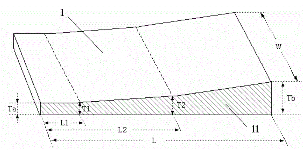
A technology of liquefied natural gas and manufacturing methods, which is applied in the field of wide and thick steel plate production, can solve problems such as prolonging the manufacturing cycle and increasing the manufacturing cost of storage tanks, and achieve the effects of reducing weight, improving production efficiency, and reducing usage
- Summary
- Abstract
- Description
- Claims
- Application Information
AI Technical Summary
Problems solved by technology
Method used
Image
Examples
Embodiment 1
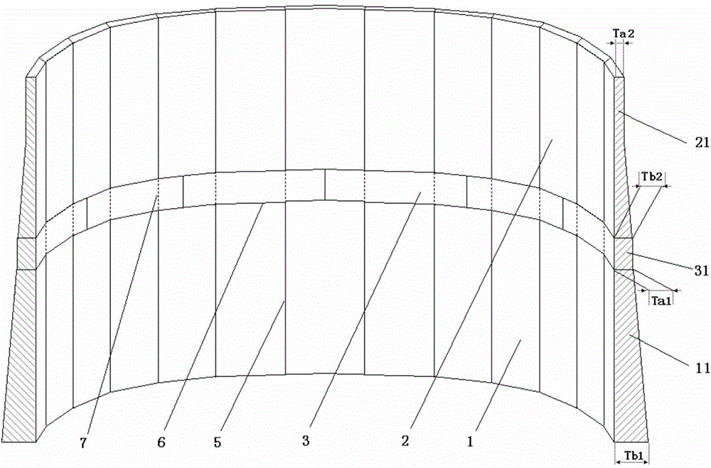
[0078] In this embodiment, an inner tank wall structure of an LNG storage tank with a theoretical capacity of 160,000 cubic meters and a steel plate for the tank wall are designed.
[0079] In the existing design, the inner tank wall structure of such an LNG storage tank with a design capacity of 160,000 cubic meters should be as follows Image 6 Shown. In the figure, 3 is a schematic diagram of the plate surface of the equal-thickness steel plate for the tank wall. 31, 32, 33, 34, 35, 36, 37, 38, 39, 310, 311 and 312 are the first bottom-up tank walls respectively. Schematic diagram of the thickness section of the steel plate of the layer, the second layer, the third layer, the fourth layer, the fifth layer, the sixth layer, the seventh layer, the eighth layer, the ninth layer, the tenth layer, the eleventh layer and the twelfth layer , 5 is the longitudinal weld between the wall panels, and 6 is the circular weld between the wall panels. It can be seen from the figure that the...
Embodiment 2
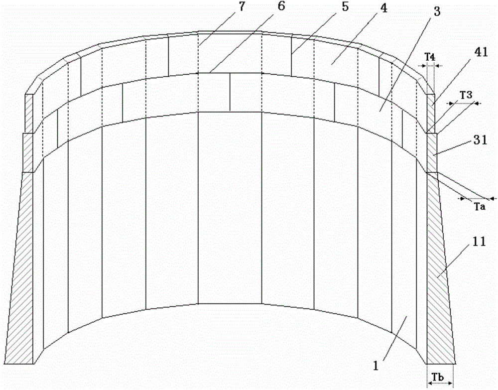
[0125] In this embodiment, an inner tank wall structure of an LNG storage tank with a theoretical capacity of 100,000 cubic meters and a steel plate for the tank wall are designed.
[0126] In the existing traditional design, the inner tank wall structure of such an LNG storage tank with a design capacity of 100,000 cubic meters should be as follows Figure 7 Shown. In the figure, 3 is a schematic diagram of the plate surface of a steel plate of equal thickness for the tank wall. 31, 32, 33, 34, 35, 36, 37, 38, 39 and 310 are the first and second layers of the tank wall from bottom to top, respectively , The third layer, the fourth layer, the fifth layer, the sixth layer, the seventh layer, the eighth layer, the ninth layer and the tenth layer of the steel plate thickness section diagram, 5 is the longitudinal weld between the wall panels, 6 is Annular weld between wall panels. It can be seen from the figure that the thickness of the tank wall in the traditional 100,000 cubic m...
PUM
| Property | Measurement | Unit |
|---|---|---|
| perimeter | aaaaa | aaaaa |
| thickness | aaaaa | aaaaa |
Abstract
Description
Claims
Application Information
 - R&D
- Intellectual Property
- Life Sciences
- Materials
- Tech Scout
- Unparalleled Data Quality
- Higher Quality Content
- 60% Fewer Hallucinations
Browse by: Latest US Patents, China's latest patents, Technical Efficacy Thesaurus, Application Domain, Technology Topic, Popular Technical Reports.
© 2025 PatSnap. All rights reserved.Legal|Privacy policy|Modern Slavery Act Transparency Statement|Sitemap|About US| Contact US: help@patsnap.com


