A Narrow Gap Welding Method for Standing Seam Position of Liquid Natural Gas Storage Tank

A technology of liquefied natural gas and welding method, which is applied in the direction of welding equipment, welding accessories, welding rod characteristics, etc., can solve the problems of low welding efficiency of ordinary TIG welding, difficult clamping of standing seam position, and difficult realization of actual production, etc., and achieves the improvement of welding construction Excellent efficiency, metallurgical properties and mechanical properties, and the effect of improving production efficiency

Active Publication Date: 2018-04-13
SHANDONG UNIV
View PDF6 Cites 0 Cited by
  • Summary
  • Abstract
  • Description
  • Claims
  • Application Information

AI Technical Summary

Problems solved by technology

[0005] At present, the standing seam of the LNG tank body is completed by traditional manual arc welding, but applying TIG welding to the standing seam of 9% Ni steel is difficult for the current technology: the welding efficiency of ordinary TIG welding is low, and for such a large The actual production of the storage tank is difficult to realize; heat input control is difficult, only by controlling the heat input 7 ~ 35KJ / cm, and the interlayer temperature below 100 ℃, can the low temperature toughness of the 9% steel welded joint be guaranteed, which constitutes a contradiction with the welding efficiency; the standing seam position Clamping is difficult. Welding 9% Ni steel must prevent arc magnetic blowing, so magnetic clamps cannot be used for clamping.

Method used


Image

  • A Narrow Gap Welding Method for Standing Seam Position of Liquid Natural Gas Storage Tank
  • A Narrow Gap Welding Method for Standing Seam Position of Liquid Natural Gas Storage Tank
  • A Narrow Gap Welding Method for Standing Seam Position of Liquid Natural Gas Storage Tank

Examples


Embodiment 1

[0032] A narrow gap welding method at the standing seam position of a liquid natural gas storage tank, comprising the following steps:

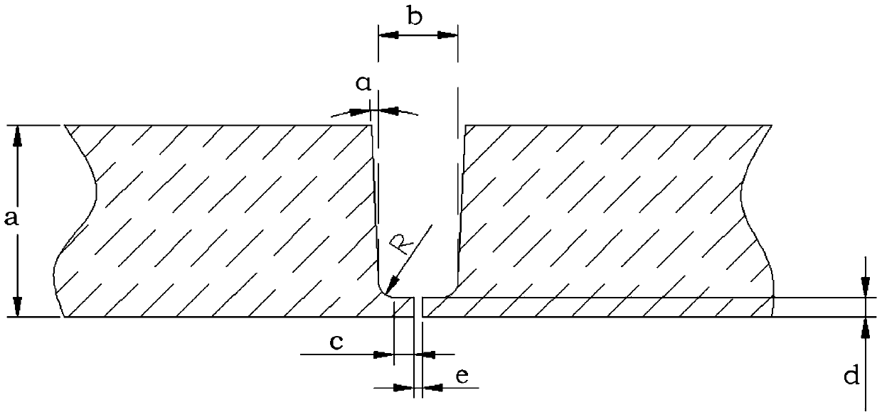
[0033] (1), Groove treatment: such as figure 1 As shown, the thickness of the plate is a=24mm, and the U-shaped groove with a narrow gap is opened for the thick plate, the groove gap b=10mm, blunt edges are reserved, and the groove is polished and derusted; the groove size is: ①The transition radius of the bottom arc R=2.0mm; ②The protruding length of the blunt edge c=2.5mm, the thickness of the blunt edge d=2.5mm; ③The gap e=1.0mm; ④The groove angle α=2.5°;

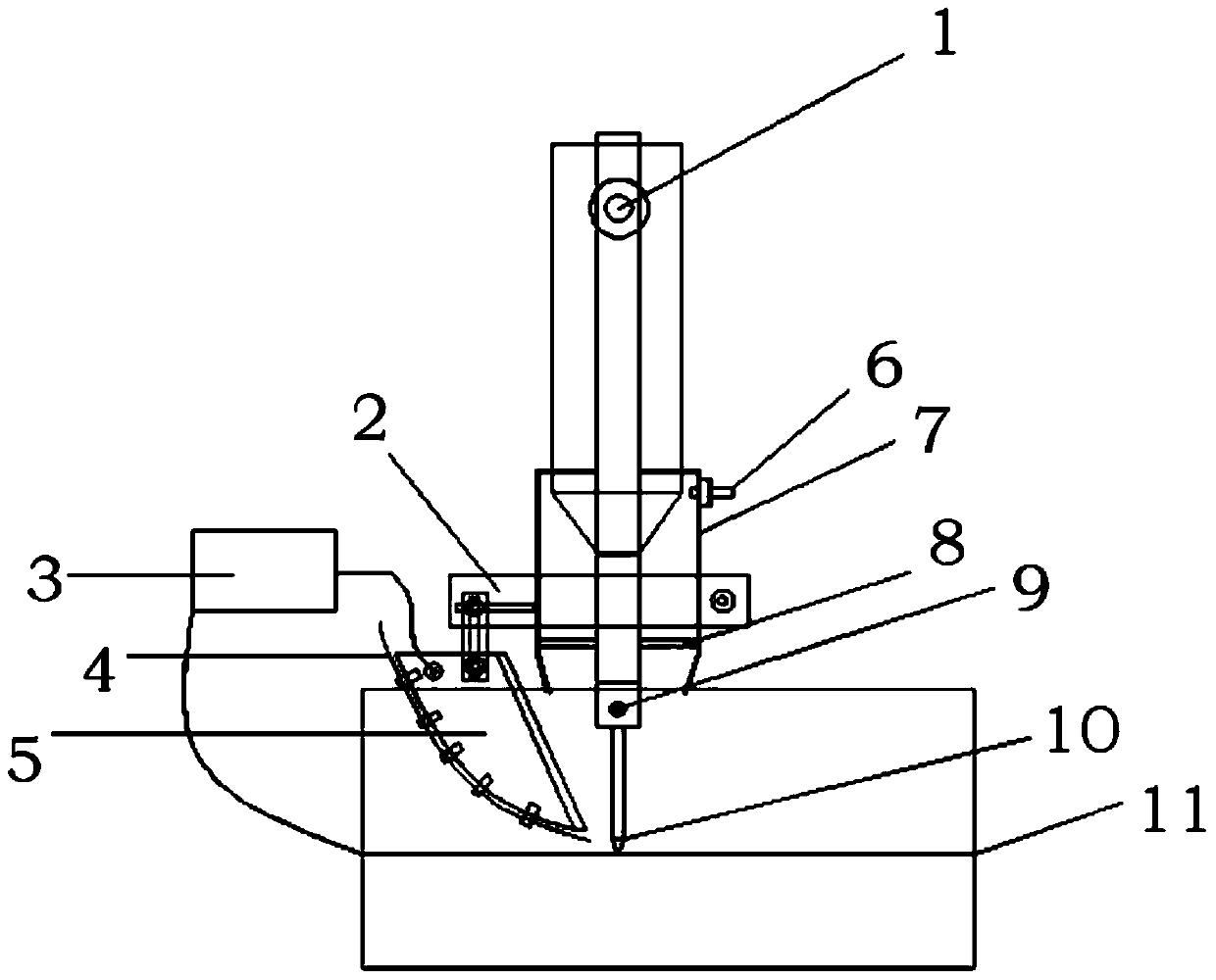
[0034] (2) Clamping: Use the existing LNG liquid storage tank wall-mounted trolley to fix two racks and brackets on the tank wall, and use the racks and brackets to achieve relative fixation between the crawling welding robot and the storage tank to achieve stable installation. Clamping, the clamping error is less than 1mm;

[0035] (3) Welding of opposite seams:

[0036] Use the wal...

Embodiment 2

[0042] A narrow gap welding method at the vertical seam position of a liquid natural gas storage tank, the steps are as described in Example 1, the difference is that the wire feeding speed is 300cm / min, the arc voltage is 12V, the welding wire preheating current is 70A, and the welding speed is 6cm / min. min, the heat input is controlled below 33KJ / cm.


PUM


Abstract

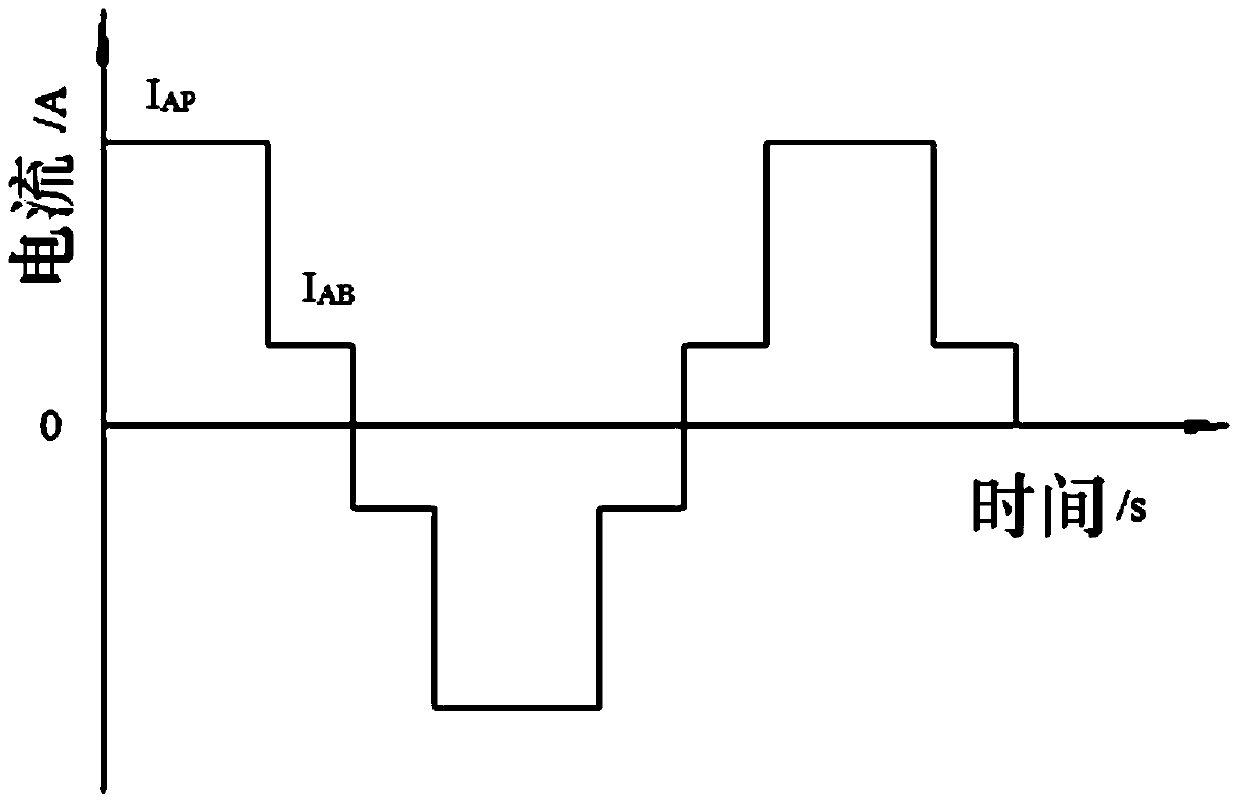
The invention relates to a narrow gap welding method for a vertical weld position of a liquified natural gas storage tank, and belongs to the technical field of welding. A U-shaped groove is formed in a to-be-processed plate, the use amount of filler metal is reduced; the groove is subjected to polishing rust removal; a rack and a bracket are fixed at the vertical weld position of the liquified natural gas storage tank; a wall-hung trolley takes a crawl welding robot to advance, and automatic vertical welding of 9% Ni steel is realized through narrow gap hot wire TIG (Tungsten Inert Gas) welding; the crawl welding robot controls a swinging welding process of a welding gun; by employing accurate centring of a tungsten electrode welding gun, good fusion of the side wall is realized; by employing an alternating current pulse hot wire TIG welding technique, with the adoption of a double step alternating current pulse welding current wave form having alternating current and pulse functions is used, and through the adjustment of welding current and pulse frequency, lower weld heat input is accurately controlled, high-efficiency and high-quality welding preparation of the liquified natural gas storage tank is realized.

Description

technical field [0001] The invention relates to a narrow gap welding method for the vertical seam position of a liquefied natural gas storage tank, and belongs to the field of welding technology. Background technique [0002] In recent years, with the rapid growth of liquefied natural gas consumption worldwide, there is a huge demand for 9% Ni steel and its welding technology, the key material for manufacturing LNG storage tanks. 9% Ni steel is considered to be the best material for manufacturing low temperature pressure vessels / storage tanks due to its excellent low temperature performance and welding performance. The main problem of welding 9% Ni steel is to ensure the low temperature toughness of welded joints, prevent welding cracks, and prevent arc magnetism. Issues such as partial blowing, which are related to the type of welding material, welding heat input, and welding process. At present, the main welding methods for welding 9% Ni steel are electrode arc welding (S...

Claims


Application Information

Patent Timeline
Patent Type & Authority Patents(China)
IPC IPC(8): B23K9/167B23K9/02B23K9/235B23K9/28B23K9/32B23K101/12
CPCB23K9/0213B23K9/167B23K9/235B23K9/28B23K9/32B23K2101/125
Inventor 贾传宝闫强强
Owner SHANDONG UNIV
Why Eureka
Try Eureka