Power supply module test device

A technology of power module and testing equipment, which is applied in the field of power module testing equipment, can solve the problem that the ball power module without pins and solders cannot be detected, and achieve the effect of not damaging the contacts

Inactive Publication Date: 2016-04-27
LUOYANG INST OF ELECTRO OPTICAL EQUIP OF AVIC
View PDF6 Cites 3 Cited by
  • Summary
  • Abstract
  • Description
  • Claims
  • Application Information

AI Technical Summary

Problems solved by technology

[0003] The purpose of the present invention is to improve a power module testing equipment to solve t

Method used


Image

  • Power supply module test device
  • Power supply module test device
  • Power supply module test device

Examples


Example Embodiment

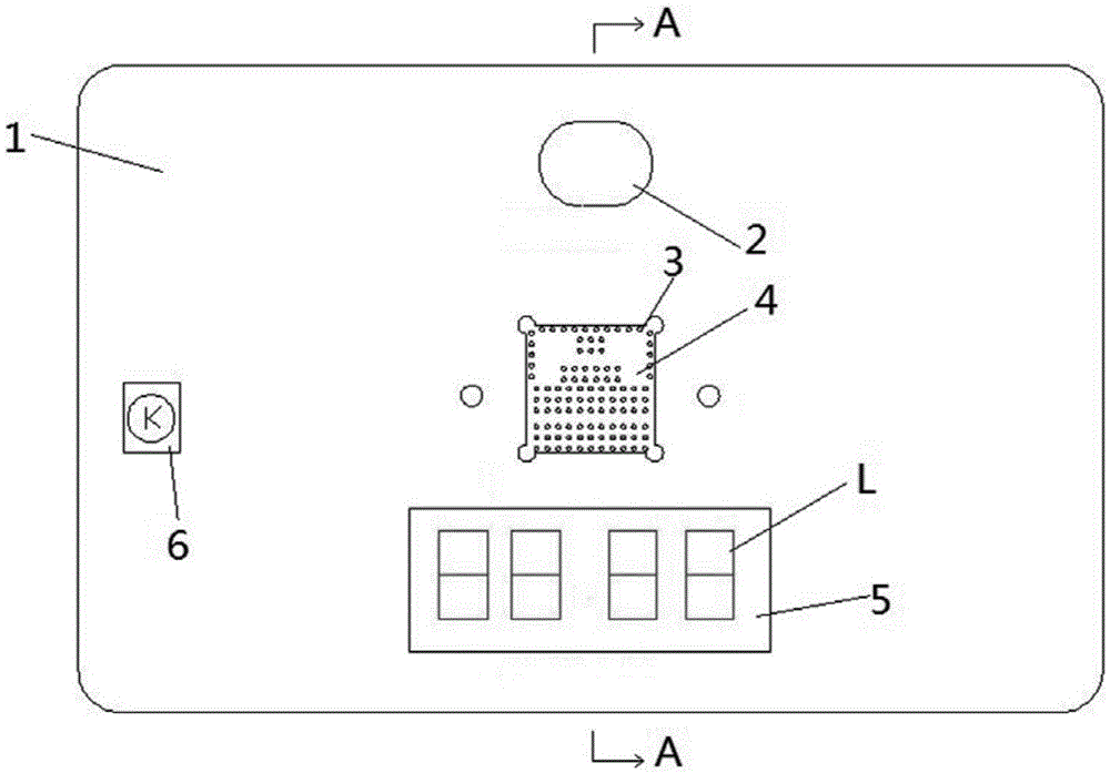
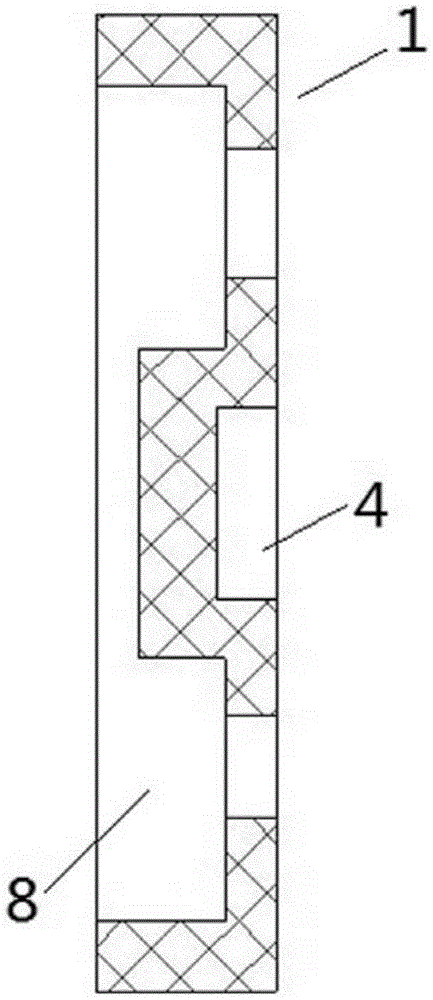
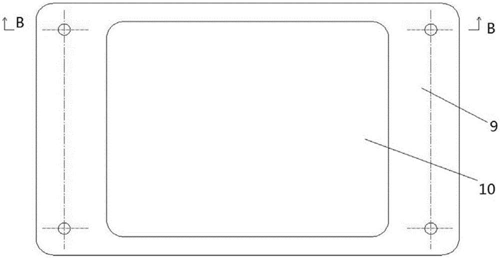
[0021] An embodiment of a power module testing device is as follows Figures 1 to 5 Shown: including a test base, the test base includes an upper cover 1, a lower cover 9 and a circuit board (not shown in the figure), an upper cover accommodating cavity 8 is provided on the lower surface of the upper cover 1, and the lower cover The upper surface of the board 9 is provided with a lower cover plate accommodating cavity 10, the upper and lower accommodating cavities form a space for the circuit board to be arranged, the upper and lower cover plates are assembled together by screws, and the circuit board is arranged between the upper and lower cover plates. , which can protect the circuit board. The circuit board is provided with a test circuit, and the lower cover is provided with vertically arranged contacts (not shown in the figure). and a floating contact portion mounted on the mounting portion by means of a spring, and the mounting portion is connected to the test circuit b...


PUM


Abstract

The invention relates to a power supply module test device, comprising a test base. The test base is provided with a test circuit and a contact member which is used for matching with contacts of the power supply module in a press-contact mode. The contact member is electrically connected to the test circuit. During usage, the power supply module is connected to the test circuit through the pressing match between the contact member of the test base and the contacts of the power supply module, the contacts are guaranteed not to be damaged, and at the same time, a quick test of the power supply module is realized.

Description

technical field [0001] The invention relates to a power module testing device. Background technique [0002] The LTM4600 power module is a contact array packaged power supply DC / DC conversion chip, the input voltage range is 4.5V-20V, the output voltage range can be from 0.6V-5V (determined by a single peripheral resistor), and the maximum output current can reach 10A , the peak current can reach 14A, the output voltage adjustment rate can reach 1.5%, the highest efficiency can reach 92%, the transient response speed is super fast, the typical switching frequency is 850KHz, there is a signal output of good power supply, and there is output overvoltage Protection and optional short-circuit shutdown timer. However, this power module has no pins and no solder balls, and its bottom is a square plate electrode in an array state. The contact density of the electrodes is high. Or solder balls are welded in the test circuit for detection), the second screening cannot be carried ou...

Claims


Application Information

Patent Timeline
IPC IPC(8): G01R31/40
CPCG01R31/40
Inventor 王家波盛军赵桂花吴晓鸣刘波
Owner LUOYANG INST OF ELECTRO OPTICAL EQUIP OF AVIC
Why Eureka
Try Eureka