Warp correction method for sputtering target with backing plate

A sputtering target and backplate technology, which is applied in sputtering plating, metal material coating process, ion implantation plating, etc., can solve problems such as time-consuming and achieve the effect of improving production efficiency

Inactive Publication Date: 2016-04-27
TANAKA PRECIOUS METAL IND
View PDF6 Cites 10 Cited by
  • Summary
  • Abstract
  • Description
  • Claims
  • Application Information

AI Technical Summary

Problems solved by technology

[0011] In the technique described in Patent Document 5, it is necessary to intermittently measure the warpage that occurs while cooling, and to add reverse warpage that cancels out the warpage that occurs every time, which takes time and effort.

Method used


Image

  • Warp correction method for sputtering target with backing plate
  • Warp correction method for sputtering target with backing plate
  • Warp correction method for sputtering target with backing plate

Examples


Embodiment 1

[0071] In this embodiment 1, a diameter of 158.75 mm, a thickness of 3.17 mm and a composition of Fe-35Pt-15SiO 2 -10C sputtering target (SiO 2 , C relative to the overall target volume ratio are 38.47%, 4.99%, SiO 2 The volume ratio of the sum of C and C to the entire target material is 43.46 vol%). The sputtering target is SiO 2 and C dispersed in the matrix metal (FePt alloy) obtained by the complex.

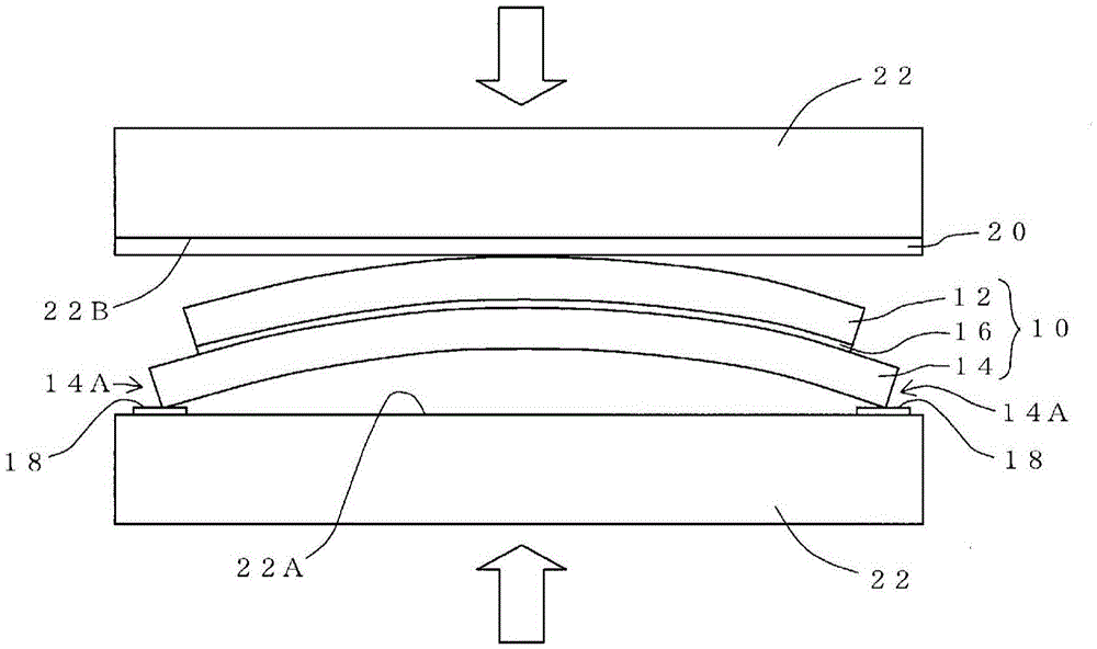
[0072] An oxygen-free copper back plate with a diameter of 165.1 mm and a thickness of 3.18 mm was attached to this sputtering target using indium. When using indium for installation, heat the sputtering target, oxygen-free copper backplane, and indium to about 300°C, make the molten indium intervene between the sputtering target and oxygen-free copper backplane, cool to room temperature to make the indium Cured to bond the sputter target to the oxygen-free copper backplate.

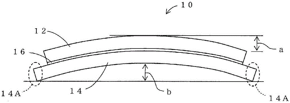
[0073] The amount of warping on the back plate side of the BP-attached target after cooling to ...

Embodiment 2

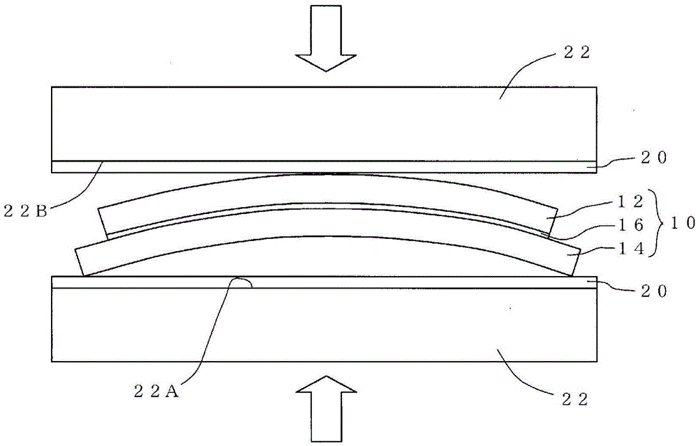
[0098] In Example 1, the press pressure to be applied was increased in four steps from 0.50MPa→2.48MPa→4.95MPa→14.86MPa, but in Example 2, pressurization at 14.86MPa was performed for only 10 minutes , pressurize in one stage.

[0099] Except for this, experiments were performed under the same conditions as in Example 1. In addition, in this Example 2, the same BP-attached target as in Example 1 was used.

[0100] In this Example 2, the amount of BP warping was measured after pressurization of 14.86 MPa for 10 minutes, and the amount of BP warping was 0.07 mm. The value of this BP warping amount is the same as the value of the BP warping amount after pressurization of 14.86 MPa was performed for 10 minutes in Example 1. Therefore, it can be considered that if the highest value of the pressing pressure finally applied and the time for applying the highest value of the pressing pressure are approximately the same, no matter whether the pressing force is gradually increased and...

Embodiment 3

[0102] In this embodiment 3, a diameter of 153 mm, a thickness of 3 mm and a composition of 85 (Co-40Cr)-15TiO 2 The sputtering target (TiO 2 The volume ratio to the entire target material is 33.02 vol%). The sputtering target is TiO 2 A composite obtained by dispersing in a base metal (CoCr alloy).

[0103] An oxygen-free copper back plate with a diameter of 161 mm and a thickness of 4 mm was attached to this sputtering target using indium. When using indium for installation, heat the sputtering target, oxygen-free copper backplane, and indium to about 300°C, so that the molten indium is interposed between the sputtering target and the oxygen-free copper backplane, and cool to room temperature to solidify the indium , and the sputtering target is bonded to the oxygen-free copper backplane.

[0104] The amount of warpage on the back plate side of the bonded target with BP after cooling to room temperature ( figure 1 The indicated BP warpage b) is 0.23 mm.

[0105] Next, ...


PUM

PropertyMeasurementUnit
thicknessaaaaaaaaaa
thicknessaaaaaaaaaa
thicknessaaaaaaaaaa

Abstract

Provided is a simple warp correction method which can correct warping in a warped sputtering target with a backing plate (BP). A pressing device is provided with an upper pressing surface (22B) and a lower pressing surface (22A) opposing each other in the vertical direction, and this warp correction method involves: an arrangement step for arranging the BP-attached sputtering target (10) on the lower pressing surface (22A) with the target (12) side up, and for arranging spacers (18) between the lower pressing surface (22A) and the outside edges (14A) of the backing plate (14) of the BP-attached target (10); and, after the arrangement step, a pressing step for pressing the BP-attached target (10) in the vertical direction by means of the pressing device. The target (12) is a composite comprising metal oxides and / or carbon dispersed in the matrix metal.

Description

technical field [0001] The present invention relates to a method for correcting warpage of a sputtering target with a backing plate (hereinafter, sometimes abbreviated as “the method for correcting warping”). A warpage correction method for warpage of a shooting target (hereinafter, sometimes referred to as "BP-coated target"). Background technique [0002] In order to attach to a sputtering apparatus or to cool a target being sputtered, a sputtering target (hereinafter, sometimes simply referred to as a “target”) may be attached to a sputtering apparatus with a back plate attached thereto. [0003] When installing the back plate to the sputtering target, the current situation is that the following method is often used: the sputtering target and the back plate are heated to a temperature at which indium will melt (for example, about 250-300°C), and the molten indium is interposed between the sputtering The sputtering target and the back plate are cooled to room temperature ...

Claims


Application Information

Patent Timeline
Patent Type & Authority Applications(China)
IPC IPC(8): C23C14/34
CPCC23C14/3414H01J37/3435H01J37/3423C23C14/0605C23C14/08H01J37/3429
Inventor 伊藤治长岛卓哉青野雅广山本孝充
Owner TANAKA PRECIOUS METAL IND
Why Eureka
Try Eureka