Microfluidic chip, hemocyte separation method and system, and preparation method of system

A microfluidic chip and chip technology, which is applied in the field of blood cell separation, can solve the problems of low separation efficiency, miniaturization and insufficient lightweight, and achieve the effects of reducing clogging, realizing light weight, and realizing miniaturization.

Active Publication Date: 2016-05-04
TSINGHUA UNIV
12 Cites 24 Cited by

AI-Extracted Technical Summary

Problems solved by technology

[0003] The purpose of the present invention is to provide a microfluidic chip, a whole blood cell separation system based on the chip, a manufacturing method of the system and a method for separating blood cells by using the...

Method used

The manufacture method of whole blood blood cell separation system described in the embodiment of the present invention, the whole blood blood cell separation system made comprises microfluidic chip, utilizes the characteristics of the bidirectional drive of the peristaltic micropump of microfluidic chip, can quickly Change the flow direction of the fluid in the chip, push out the blood cells blocked in the micropores of the filter membrane, effectively avoid the blockage of the porous filter membrane; use the combination of cross-flow filtration and dead-end filtration to filter blood cells, further reduce filtration The clogging of the membrane can realize the separation of a large number of blood samples; the bidirectional peristaltic micropump is integrated on the microfluidic chip, and the input and output of the sample do not need an external fluid drive source, which realizes the miniaturization and light weight of the system, and provides fast and high-pass Quantitative blood separation provides an effective means.
The method for carrying out whole blood blood cell separation described in the embodiment of the present invention, used whole blood blood cell separation system comprises microfluidic chip, utilizes the characteristics of the bidirectional drive of the peristaltic micropump of microfluidic chip, can change chip quickly The flow direction of the internal fluid pushes out the blood cells blocked in the micropores of the filter membrane in reverse, effectively avoiding the clogging of the porous filter membrane; the blood cells are filtered by a combination of cross-flow filtration and dead-end filtration to further reduce the loss of the filter membrane Blockage can realize the separation of a large number of blood samples; the bidirectional peristaltic micropump is integrated on the microfluidic chip, and the input and output of the sample do not require an external fluid drive source, which realizes the miniaturization and light weight of the system; in the process of circulating filtration, there is no need to introduce Additional buffer reduces the consumption of buffer; by controlling the operation of the micropump and the opening and closing of the microvalve, the work of sample injection, cell separation, target...

Abstract

The invention discloses a microfluidic chip, a whole blood hemocyte separation system based on the chip, a preparation method of the system and a method for separating whole blood hemocytes by using the system, is used for separating the hemocytes, can overcome the defects of low separation efficiency and insufficient miniaturization and lightweight in the prior art, and meets on-site real-time blood sample separation requirements. The chip is prepared by successively bonding a substrate layer containing a main flow channel structure with a microporous filter membrane layer and a flexible polymer layer containing an upper-layer flow channel structure, and a micro-channel system is formed in the chip; the micro-channel system includes a micro-pump area, a circulation area, a first channel, a second channel, a third channel, and a filtering area formed by the main flow channel structure, the microporous filter membrane layer and the upper-layer flow channel structure.

Application Domain

Technology Topic

Image

  • Microfluidic chip, hemocyte separation method and system, and preparation method of system
  • Microfluidic chip, hemocyte separation method and system, and preparation method of system
  • Microfluidic chip, hemocyte separation method and system, and preparation method of system

Examples

  • Experimental program(1)

Example Embodiment

[0050] In order to make the objectives, technical solutions, and advantages of the embodiments of the present invention clearer, the following will clearly describe the technical solutions in the embodiments of the present invention with reference to the accompanying drawings in the embodiments of the present invention. Obviously, the described embodiments are the present invention. Invented some embodiments, but not all embodiments. Based on the embodiments of the present invention, all other embodiments obtained by those of ordinary skill in the art without creative work shall fall within the protection scope of the present invention.
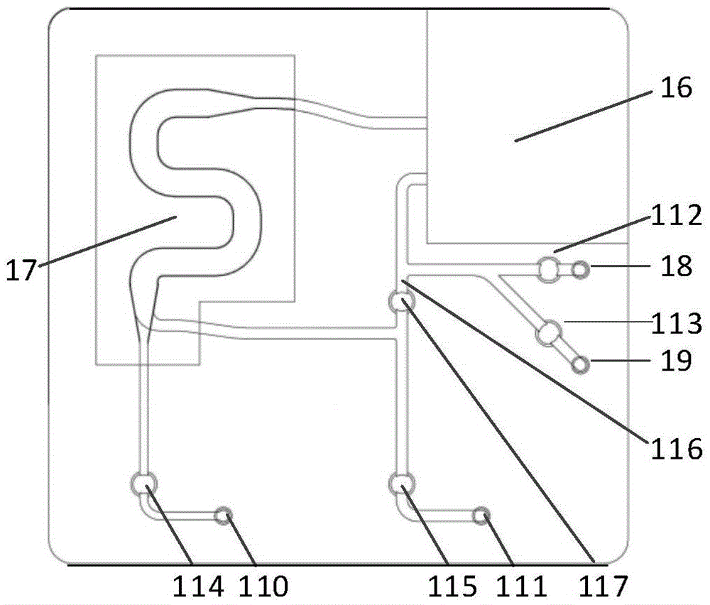
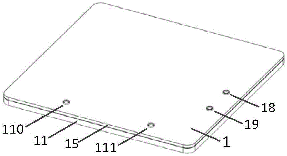
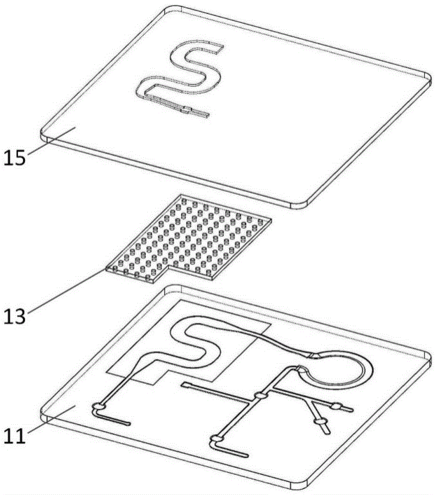
[0051] Such as Figure 1 to Figure 3 As shown, this embodiment discloses a microfluidic chip. The chip is composed of a microporous filter film layer 13, a substrate layer 11 containing a main flow channel structure (the material is a non-magnetic, transparent material plate) and an upper layer flow The flexible polymer layer 15 of the channel structure is formed by bonding the substrate layer 11 containing the main flow channel structure to the microporous membrane layer 13 and the flexible polymer layer 15 containing the upper flow channel structure successively , And form a micro channel system inside; among them,
[0052] The micro channel system includes: a micro pump area 16, a circulation area 116, a first channel, a second channel, a third channel, and a main flow channel structure, a microporous membrane layer 13 and an upper flow channel structure In the filter region 17, the end of one channel of the two layers of channels in the filter region 17 is connected to the first channel, and the end of the other channel is connected to the second channel, and the second channel is connected to the The circulation zone 116 is in communication, the circulation zone 116 and the micropump zone 16 are connected by a channel, and the third channel is in communication with the channel connecting the circulation zone 116 and the micropump zone 16, and the micropump zone 16 is connected with The filter area 17 is connected by a channel, the end of the first channel is provided with a first outlet and a first outlet microvalve corresponding to the first outlet, and the end of the second channel is provided with a second outlet and The second outlet microvalve corresponding to the second outlet, one of the first outlet and the second outlet is the target cell outlet, the other is the waste liquid outlet, and the end of the third channel is provided with blood The inlet 18, the buffer inlet 19, the blood inlet microvalve 112 corresponding to the blood inlet 18 and the buffer inlet microvalve 113 corresponding to the buffer inlet 19, the circulation area 116 communicates with the second channel A microvalve 117 for the circulation area is provided at the position, and the flexible polymer layer 15 containing the upper flow channel structure penetrates the flexible polymer layer 15 containing the upper flow channel structure corresponding to the blood inlet 18, the buffer inlet 19, The target cell outlet 110 and the waste liquid outlet 111 are respectively provided with a first through hole, a second through hole, a third through hole and a fourth through hole. The first through hole, the second through hole, the third through hole and the The four through holes are vertical through holes. The first through hole and the second through hole are connected to the third channel through the blood inlet 18 and the buffer inlet 19, respectively. The third through hole and the fourth through hole are respectively The target cell outlet 110 and the waste liquid outlet 111 are respectively connected to the channel corresponding to the target cell outlet and the channel corresponding to the waste liquid outlet, and the micropump area 16 is provided with a bidirectional peristaltic micropump.
[0053] The microfluidic chip according to the embodiment of the present invention utilizes the bidirectional driving characteristic of the peristaltic micropump to quickly change the flow direction of the fluid in the chip, push out the blood cells blocked in the pores of the filter membrane, and effectively avoid the porous filter membrane. The blockage of blood cells is filtered by a combination of cross-flow filtration and dead-end filtration to further reduce the blockage of the filter membrane, which can realize the separation of a large number of blood samples; the two-way peristaltic micropump is integrated on the microfluidic chip, and the input and output of the sample No external fluid driving source is needed, which realizes the miniaturization and light weight of the system, and provides an effective means for rapid and high-throughput blood separation on site. The chip can directly separate target cells from undiluted whole blood, and Realize the direct delivery of target cells to subsequent detection modules.
[0054] Optionally, see figure 1 with image 3 In another embodiment of the microfluidic chip of the present invention, the end of the upper channel of the filter region 17 is connected to the first channel, the end of the lower channel is connected to the second channel, and the first outlet Is the target cell outlet 110, the first outlet microvalve is the target cell outlet microvalve 114, and the third through hole and the fourth through hole respectively pass through the target cell outlet 110 and the waste liquid outlet 111 to connect with the first groove The road is connected to the second channel.
[0055] Such as image 3 Shown is a layered explanatory diagram of a microfluidic chip provided by another embodiment of the present invention. The chip includes a base layer with a main flow channel structure and a microporous filter membrane layer, which can be bonded by thermocompression and then surface treatment Bonded with a flexible polymer layer containing an upper flow channel structure.
[0056] Optionally, such as Figure 4 Shown is a layered explanatory diagram of a microfluidic chip provided by another embodiment of the present invention. The end of the upper channel of the filter area is connected to the second channel, and the end of the lower channel is connected to the first channel , The first outlet is a waste liquid outlet, the first outlet microvalve is a waste liquid outlet microvalve, and the third through hole and the fourth through hole respectively pass through the target cell outlet and the waste liquid outlet to communicate with the first The second channel is connected to the first channel.
[0057] Optionally, such as Figure 5 Shown is a layered explanatory diagram of a microfluidic chip provided by another embodiment of the present invention. The flexible polymer layer 15 including the upper flow channel structure includes:
[0058] The double-sided adhesive structure layer 140 containing the upper flow channel structure and the flexible polymer layer 150 are included in the chip by sequentially bonding the microporous filter membrane layer 13 and the substrate layer 11 containing the main flow channel structure to Together, the flexible polymer layer 150 and the microporous filter membrane layer 13 are bonded together through the double-sided adhesive structure layer 140 containing the upper flow channel structure, and the flexible polymer layer 150 and the main flow channel are bonded together. The structured substrate layer 11 is made by bonding together by surface treatment.
[0059] In this embodiment, the provision of a micro-channel system in the microfluidic chip specifically refers to the provision of a micro-channel system on the upper surface of the substrate layer 11, or a micro-channel system on the lower surface of the flexible polymer layer 15. Alternatively, a micro-channel system is provided on the double-sided adhesive structure layer 140.
[0060] Optionally, such as Image 6 Shown is a layered explanatory diagram of a microfluidic chip provided by another embodiment of the present invention. The chip also includes: a double-sided adhesive layer 12, and the flexible polymer layer 15 containing the upper flow channel structure includes :Contains the double-sided adhesive structure layer 140 and the flexible polymer layer 150 of the upper flow channel structure,
[0061] In the chip, the microporous filter membrane layer 13 and the substrate layer 11 containing the main flow channel structure are bonded together through the double-sided adhesive layer 12 to bond the flexible polymer layer 150 and the micro The pore filter membrane layer 13 is bonded together by the double-sided adhesive structure layer 140 containing the upper flow channel structure, and the flexible polymer layer 150 and the substrate layer 11 containing the main flow channel structure are bonded to each other by surface treatment. Made together.
[0062] Optionally, such as Figure 7 Shown is a layered explanatory diagram of a microfluidic chip provided by another embodiment of the present invention. The substrate layer 11 containing the main flow channel structure includes: a substrate layer 118 and a double-sided tape containing the main flow channel structure The adhesive layer 120, the flexible polymer layer 15 containing the upper flow channel structure includes: a double-sided adhesive structure layer 140 containing the upper flow channel structure and a flexible polymer layer 150,
[0063] In the chip, the microporous filter film layer 13 and the substrate layer 118 are bonded together through the double-sided adhesive layer 120 in sequence, and the flexible polymer layer 150 and the microporous filter film layer 13 are passed through The double-sided adhesive structure layer 140 containing the upper flow channel structure is bonded together, and the flexible polymer layer 150 and the substrate layer 118 are bonded together by surface treatment.
[0064] Optionally, see Figure 8 with Picture 9 In another embodiment of the microfluidic chip of the present invention, the flexible polymer layer is a polymer layer of polydimethylsiloxane (PDMS), and the substrate is a plexiglass transparent polymer or glass, The micropump is an annular peristaltic pump or a linear peristaltic pump.
[0065] Such as Figure 8 As shown, the micropump is configured as an annular peristaltic pump, that is, the micropump area is an annular channel 161 with a gap. Such as Picture 9 As shown, the micropump is set as a linear peristaltic pump, that is, the micropump area is a linear channel 162.
[0066] See Picture 10 with 18 This embodiment discloses a whole blood blood cell separation system based on the microfluidic chip according to any one of the foregoing embodiments, including:
[0067] Microfluidic chip 1, micro pump driving device 2, micro valve driving device 3, control module 4 and power supply module 5; among them,
[0068] The micropump driving device 2 is located above the micropump area of ​​the microfluidic chip 1 and is used to provide driving force for the micropump of the microfluidic chip 1;
[0069] The microvalve driving device 3 is located above the microfluidic chip 1 and is used to open and close the corresponding microvalves of the microfluidic chip 1;
[0070] The control module 4 is used to control the rotation direction and speed of the micro pump by controlling the micro pump driving device 2 and to control the opening and closing of the micro valve by controlling the micro valve driving device 3;
[0071] The power supply module 5 is used to supply power to the micro pump driving device 2, the micro valve driving device 3 and the control module 4;
[0072] The microvalve driving device 3 includes four linearly movable structures whose lower end surfaces are flat or spherical. The four linearly movable structures of the microvalve driving device 3 are respectively aligned with one of the microfluidic chips 1 Through holes,
[0073] If the micropump is an annular peristaltic pump, the micropump driving device 2 includes a motor 21, a shaft sleeve 22 fixedly connected to the motor, a spring 23 and a steel ball 24 mounted in the shaft sleeve 22 (using the motor 21 , The separation system of the sleeve 22, the spring 23 and the steel ball 24 such as Figure 16 (Shown), if the micropump is a linear peristaltic pump, the micropump driving device 2 includes four linearly movable structures, and the linearly movable structures are electromagnets or motors capable of outputting linear displacement.
[0074] Such as Picture 11 As shown, the micro-pump driving device 2 of the linear peristaltic pump has four linearly movable structures 25, 26, 27, 28 (the separation system using linearly movable structures 25, 26, 27, 28, such as Figure 17 Shown); the linearly movable structures 25, 26, 27, 28 are electromagnets or motors capable of outputting linear displacement. The micro-pump driving device of the linear peristaltic pump can also use a high-pressure gas pneumatic pump. Micropumps can also be other pressure-driven pumps integrated on the chip.
[0075] Such as Picture 12 As shown, the microvalve driving device is a linearly movable structure 3, which is arranged above the microfluidic chip, and the linearly movable mechanism 3 is an electromagnet or a motor capable of outputting linear displacement. The lower end of the linearly movable mechanism 3 is a spherical surface.
[0076] Such as Figure 13 As shown, the microvalve driving device is a linearly movable structure 3, which is arranged above the microfluidic chip, and the linearly movable mechanism 3 is an electromagnet or a motor capable of outputting linear displacement. The lower end of the linearly movable mechanism 3 is a flat surface, and its shape is similar to that of a micro valve.
[0077] Such as Figure 14 Shown is the schematic diagram of cross-flow filtration in the blood cell separation process, and the flow direction of the main flow is parallel to the direction of the filter membrane.
[0078] Such as Figure 15 Shown is a schematic diagram of dead-end filtration in the process of blood cell separation. The flow direction of the main flow is perpendicular to the direction of the filter membrane.
[0079] In use as figure 2 , image 3 , Figure 8 , Picture 10 , Picture 12 with Figure 14 The structure shown as Figure 16 In the embodiment 1 of the whole blood cell separation system shown, the thickness of the substrate layer 11 is 0.2mm-30mm, the annular outer diameter of the annular channel 161 is 8-30mm, the width of the channel is 0.05-5mm, and the depth is 0.01-1mm. The depths of the blood inlet microvalve 112, the buffer inlet microvalve 113, the target cell outlet microvalve 114, the waste liquid outlet microvalve 115, and the circulation zone microvalve 117 are 0.01-1 mm. The lower ends of the electromagnets 31, 32, 33, 34, and 35 corresponding to each microvalve are all spherical, with a radius of 0.5-10 mm. When the target cells are leukocytes, the pore size of the microporous membrane layer 13 is 2 μm-7 μm, the porosity of the microporous membrane layer 13 is 1%-80%, and the thickness of the microporous membrane layer 13 is 5-500 μm. The thickness of the flexible polymer 15 is 0.05-3 mm. The blood inlet 18, the buffer solution inlet 19, the target cell outlet 110, and the waste solution outlet 111 have any shapes and can be arranged in any order.
[0080] In use as figure 2 , Figure 4 , Figure 8 , Picture 10 with Picture 12 The structure shown as Figure 16 In the shown embodiment 2 of the whole blood cell separation system, the difference between embodiment 2 and embodiment 1 is that in the process of blood cell separation, the buffer is continuously sucked from the buffer inlet 19, and the target cells circulate in the chip. Red blood cells and plasma with smaller size and greater deformability pass through the microporous membrane layer 13 and are discharged from the 110 outlet, and the target cells are finally discharged from the 111 outlet or injected into the subsequent detection equipment.
[0081] In use as figure 2 , image 3 , Figure 8 , Picture 10 , Picture 12 with Figure 14 The structure shown as Figure 16 In Example 3 of the whole blood cell separation system (target cells are circulating tumor cells CTCs), the difference between Example 3 and Example 1 is that the pore size of the microporous membrane layer 13 is 7μm-12μm, The porosity of the porous membrane layer 13 is 1%-80%, and the thickness of the microporous membrane layer 13 is 5-500 μm. The other structure is the same as that of Embodiment 1, and will not be repeated here.
[0082] In use as figure 2 , image 3 , Picture 9 , Picture 11 with Picture 12 The structure shown as Figure 17 In the shown embodiment 4 of the whole blood cell separation system, the difference between embodiment 4 and embodiment 1 is: the micropump adopts a linear peristaltic pump; the micropump driving mechanism 25, 26, 27, 28 moves according to a certain rule, The flexible polymer layer 15 allows the liquid in the microchannel to flow in one direction; the micropump driving mechanism 25, 26, 27, 28 is an electromagnet or a motor capable of outputting linear displacement. The other structure is the same as that of Embodiment 1, and will not be repeated here.
[0083] In use as figure 2 , image 3 , Figure 8 , Picture 10 , Figure 13 with Figure 14 The structure shown as Figure 16 In the embodiment 5 of the whole blood cell separation system shown, the difference between embodiment 5 and embodiment 1 is: blood inlet microvalve 112, buffer inlet microvalve 113, target cell outlet microvalve 114, waste liquid outlet microvalve The microvalve 115 and the circulation zone microvalve 117 are grooves in any shape with a depth of 0.01-3mm. The lower ends of the electromagnets 31, 32, 33, 34, and 35 corresponding to each microvalve are all flat, and their shape is similar to that of the microvalve. The other structure is the same as that of Embodiment 1, and will not be repeated here.
[0084] In the whole blood cell separation system according to the embodiment of the present invention, the microfluidic chip used in the microfluidic chip utilizes the characteristics of the bidirectional drive of the peristaltic micropump, which can quickly change the flow direction of the fluid in the chip and reverse the blood cells blocked in the micropores of the filter membrane. It can effectively avoid the clogging of the porous filter membrane; the combination of cross-flow filtration and dead-end filtration is used to filter blood cells to further reduce the clogging of the filter membrane and realize the separation of a large number of blood samples; the two-way peristaltic micropump is integrated in the micro flow On the control chip, the sample input and output do not require an external fluid drive source, which realizes the miniaturization and light weight of the system, and provides an effective means for rapid and high-throughput blood separation on site.
[0085] Such as Figure 19 As shown, this embodiment discloses a method for manufacturing the whole blood cell separation system described in the foregoing embodiment, including:
[0086] S11. Fabricate microchannels on the substrate layer, fabricate microchannels on the flexible polymer layer, bond the microporous membrane layer and the substrate layer together, and bond the flexible polymer layer and the substrate layer together Together, form a micro channel system;
[0087] S12. Punch holes in the flexible polymer layer to make through holes corresponding to the blood inlet, buffer inlet, target cell outlet, and waste liquid outlet to form a microfluidic chip;
[0088] S13. Arrange a micropump driving device above the micropump area of ​​the microfluidic chip (in a specific embodiment, the steel ball of the micropump driving device is aligned with the annular channel of the micropump area);
[0089] S14. Arrange four linearly movable structures above the microfluidic chip, so that each linearly movable structure is aligned with a through hole respectively, wherein the four linearly movable structures constitute a microvalve driving device;
[0090] S15. Arrange a control module and a power supply module around the microfluidic chip, connect the control module with the micropump driving device and the microvalve driving device, and connect the power supply module with the micropump driving device and the microvalve The drive device is connected to the control module.
[0091] In the method for manufacturing a whole blood cell separation system according to an embodiment of the present invention, the manufactured whole blood cell separation system includes a microfluidic chip. The bidirectional driving characteristics of the peristaltic micropump of the microfluidic chip can be used to quickly change the chip The flow direction of the fluid pushes the blood cells clogged in the pores of the filter membrane backwards, effectively avoiding the clogging of the porous filter membrane; the blood cells are filtered through a combination of cross-flow filtration and dead-end filtration to further reduce the clogging of the filter membrane , Can realize the separation of a large number of blood samples; the two-way peristaltic micropump is integrated on the microfluidic chip, and the sample input and output does not require an external fluid driving source, which realizes the miniaturization and light weight of the system, which is a fast and high-throughput blood separation on site Provide effective means.
[0092] Such as Picture 20 As shown, this embodiment discloses a method for separating whole blood cells by using the whole blood cell separation system described in the foregoing embodiment, including:
[0093] S21. Close the blood inlet microvalve, the target cell outlet microvalve, and the circulation area microvalve through the control module, open the buffer inlet microvalve and the waste liquid outlet microvalve, and control the micropump driving device to drive the micropump to rotate in the forward direction, thereby removing the buffer The fluid inlet sucks buffer (phosphate buffer, such as PBS buffer), and fills or partially fills the channel of the microfluidic chip with buffer;
[0094] S22. Close the buffer inlet microvalve through the control module, open the blood inlet microvalve, and control the micropump driving device to drive the micropump to rotate forward, so as to suck a certain amount of whole blood sample (undiluted) from the blood inlet );
[0095] S23. Close the blood inlet microvalve through the control module, open the buffer inlet microvalve, and control the micropump driving device to drive the micropump to rotate forward, so as to suck buffer from the buffer inlet and push the whole blood sample Go to the filtering area for filtering;
[0096] S24. After filtering for a period of time, close the buffer inlet microvalve and the waste liquid outlet microvalve through the control module, open the circulation zone microvalve, and control the micropump driving device to drive the micropump to rotate in reverse, thereby driving the micropump The fluid in the channel of the fluid control chip flows in the reverse direction, and the blood cells blocked in the micropores of the microporous membrane layer are pushed out in reverse;
[0097] S25, controlling the micropump driving device to drive the micropump to rotate forward through the control module, thereby driving the fluid in the channel of the microfluidic chip to circulate and filter in the microfluidic chip;
[0098] S26. Close the circulation zone microvalve through the control module, open the buffer inlet microvalve and the waste liquid outlet microvalve, and control the micropump driving device to drive the micropump to rotate in the forward direction, thereby sucking buffer from the buffer inlet , Drain the remaining red blood cells and plasma from the waste liquid outlet;
[0099] S27. Repeat steps S24 to S26 several times;
[0100] S28. Close the waste liquid outlet microvalve through the control module, open the target cell outlet microvalve, and control the micropump driving device to drive the micropump to rotate in the forward direction, thereby sucking in the buffer from the buffer inlet, and separating the separated The blood cells are pushed out from the target cell outlet, and the separated target cells are collected.
[0101] In the working process, the motor 21 of the micropump driving device 2 and the shaft sleeve 22 move toward the microfluidic chip 1, and the steel ball 24 inside the shaft sleeve 22 presses the annular channel 161; the electromagnets 31, 33, 35 are connected Close the blood inlet microvalve 112, the target cell outlet microvalve 114, and the circulation zone microvalve 117. Open the buffer inlet microvalve 113 and the waste liquid outlet microvalve 115. The motor 21 drives the shaft sleeve 22 to rotate in the forward direction. The buffer is sucked in from the buffer inlet 19 under suction, and fills the microchannel; the buffer inlet microvalve 113 is closed, the blood inlet microvalve 112 is opened, and the micropump driving device 2 drives the micropump to suck a certain amount of blood from the blood inlet 18. Sample; close the blood inlet microvalve 112, open the buffer inlet microvalve 113, the micropump continues to suck the buffer from the buffer inlet 19, and push the blood sample to the filter area 17, where the target cells of larger size are pores The filter membrane layer 13 blocks and gathers upstream of the target cell outlet microvalve 114. Red blood cells and plasma pass through the microporous filter membrane layer 13 and flow out from the waste liquid outlet 111; after filtering for a period of time, close the buffer inlet microvalve 113 and waste The liquid outlet microvalve 115 opens the circulation zone microvalve 117, and controls the motor 21 of the micropump driving device 2 to rotate in the reverse direction. The motor 21 simultaneously drives the shaft sleeve 22 and the steel ball 24 inside the shaft sleeve to rotate in the reverse direction, driving the microfluidic chip 1 The fluid in the channel flows in the reverse direction, pushing out the blood cells blocked in the micropores of the microporous membrane layer 13, effectively avoiding the clogging of the microporous membrane layer 13; does not change the opening and closing status of each microvalve, and controls the motor 21 forward rotation, the micropump drives the blood sample to circulate and filter in the chip, and the sample sequentially passes through the micropump area 16, the filter area 17, the circulation area 116 and their interconnected channels, and circulates in this way. This process does not need to introduce additional buffer; Circulation zone microvalve 117, open the buffer inlet microvalve 113 and waste outlet microvalve 115, control the motor 21 to rotate forward, continue to suck buffer from the buffer inlet 19, and discharge the remaining red blood cells and plasma from the waste outlet 111; Repeat the process of backwashing, circulating filtration and cleaning several times to further improve the separation effect of blood cells; 8. Close the waste liquid outlet microvalve 115, open the target cell outlet microvalve 114, control the motor 21 to rotate forward at a slower speed, and continue The buffer is sucked in from the buffer inlet 19, the separated blood cells are pushed out from the target cell outlet 110, and the separated target cells are collected.
[0102] In the method for separation of whole blood cells according to the embodiment of the present invention, the whole blood cell separation system used includes a microfluidic chip, and the bidirectional driving characteristics of the peristaltic micropump of the microfluidic chip can quickly change the flow of fluid in the chip. The flow direction pushes the blood cells clogged in the pores of the filter membrane in the reverse direction, effectively avoiding the clogging of the porous filter membrane; the combination of cross-flow filtration and dead-end filtration is used to filter blood cells to further reduce the clogging of the filter membrane. Realize the separation of a large number of blood samples; the two-way peristaltic micropump is integrated on the microfluidic chip, and the sample input and output does not require an external fluid drive source, which realizes the miniaturization and light weight of the system; in the process of circulating filtration, no additional buffer is required , Reducing the consumption of buffer; by controlling the operation of the micropump and the opening and closing of the microvalve, the work of sampling, cell separation, and target cell output can be realized automatically; the separation chip with integrated micropump/valve structure can be used for one-time use. It avoids the risk of cross-contamination and provides an effective means for rapid and high-throughput blood separation on site.

PUM

no PUM

Description & Claims & Application Information

We can also present the details of the Description, Claims and Application information to help users get a comprehensive understanding of the technical details of the patent, such as background art, summary of invention, brief description of drawings, description of embodiments, and other original content. On the other hand, users can also determine the specific scope of protection of the technology through the list of claims; as well as understand the changes in the life cycle of the technology with the presentation of the patent timeline. Login to view more.

Similar technology patents

Classification and recommendation of technical efficacy words

  • Avoid clogging
  • Reduce clogging

Pop-up drain

InactiveUS20080178382A1Reduce cloggingDomestic plumbingMechanical engineeringDraining tube
Owner:DELTA FAUCET COMPANY

Method for preparing mesoporous material with hydrophobic inner surface and hydrophilic outer surface

InactiveCN101733066AImprove sieving capacity and extraction efficiencyReduce cloggingOther chemical processesSilicon compoundsPeptideSurface modification
Owner:DALIAN INST OF CHEM PHYSICS CHINESE ACAD OF SCI
Why Eureka
Try Eureka