Pipe end cutting integrated machine

An all-in-one machine, pipe end technology, applied in other manufacturing equipment/tools, metal processing, manufacturing tools, etc., can solve problems such as increasing production costs, requiring more workers, and wasting manpower

Active Publication Date: 2016-05-04
SUZHOU VEDETTE IND EQUIP CO LTD
View PDF6 Cites 32 Cited by
  • Summary
  • Abstract
  • Description
  • Claims
  • Application Information

AI Technical Summary

Problems solved by technology

The processing process is cumbersome, each process requires manual auxiliary operations, and requires more workers. While wasting manpower, the production efficiency is low, which directly increases the production cost and is not conducive to automated production.

Method used


Image

  • Pipe end cutting integrated machine
  • Pipe end cutting integrated machine
  • Pipe end cutting integrated machine

Examples


Embodiment Construction

[0026] The present invention will be further described below in conjunction with the accompanying drawings and specific embodiments.

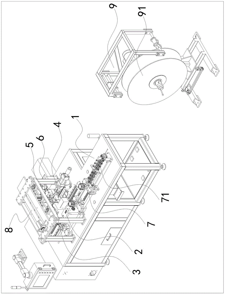
[0027] Such as Figure 1 to Figure 2 As shown, the integrated pipe end cutting machine includes a frame 1, and one side of the frame 1 is sequentially provided with a cutting mechanism 2, a chamfering mechanism 3, a nozzle processing mechanism 4, and a detection and blanking mechanism 5. It is equipped with a transport manipulator mechanism for transporting the pipe fittings from the cutting mechanism 2 to the chamfering mechanism 3, the pipe fittings from the chamfering mechanism 3 to the nozzle processing mechanism 4, and the pipe fittings from the nozzle processing mechanism 4 to the detection and unloading mechanism 5 8; The other side of the frame 1 is provided with a feeding mechanism 7 for transporting the pipe fittings to the cutting mechanism 2; the feeding mechanism 7 can be used to manually place the pipe fittings to be processed on ...


PUM


Abstract

The invention discloses a pipe end cutting integrated machine. The integrated machine comprises a rack, a cutting mechanism, a chamfering mechanism, a pipe orifice machining mechanism and a detecting and discharging mechanism are sequentially arranged at one side of the rack, and a carrying mechanical hand mechanism is arranged on the rack and used for carrying a pipe from the cutting mechanism to the chamfering mechanism, then carrying the pipe from the chamfering mechanism to the pipe orifice machining mechanism, and then carrying the pipe from the pipe orifice machining mechanism to the detecting and discharging mechanism; a feeding mechanism used for conveying the pipe to the cutting mechanism is arranged at the other side of the rack, the pipe is fed by the feeding mechanism and cut by the cutting mechanism to the needed length, the cut pipe is chamfered by the chamfering mechanism, the chamfered pipe enters the pipe orifice machining mechanism so that a pipe orifice can be machined, and after pipe orifice machining is finished, the pipe is detected and discharged by the detecting and discharging mechanism. Cutting, chamfering, pipe orifice machining, detecting and discharging are automatically conducted on the pipe.

Description

technical field [0001] The invention relates to the field of automation equipment, in particular to an integrated machine for pipe end cutting. Background technique [0002] Copper pipes are widely used in air conditioners, refrigerator refrigeration equipment, auto parts, etc. The corresponding copper pipes need to go through straightening, rounding, cutting, chamfering, pipe end processing, testing and other processes during processing. In the prior art, each The process needs to be carried out on different machines, that is, after straightening and rounding, enter the cutting machine to cut the copper pipe, collect it into the material basket after cutting, and then enter the chamfering machine for chamfering, and the chamfering is completed Finally, it is recycled into the material basket, and then enters the subsequent pipe end processing. After the processing is completed, it is recycled into the material basket and then enters the testing mechanism for product qualifi...

Claims


Application Information

Patent Timeline
Patent Type & Authority Applications(China)
IPC IPC(8): B23P23/02B23Q7/00B23Q7/04B23Q7/10
CPCB23P23/02B23Q7/00B23Q7/04B23Q7/10
Inventor 王强王军
Owner SUZHOU VEDETTE IND EQUIP CO LTD
Why Eureka
Try Eureka