Plastic-stone modeled reinforcing layer and construction method thereof

A construction method and reinforcement layer technology, which is applied in the construction of plastic stone molding reinforcement layers and the field of plastic stone molding reinforcement layers, can solve problems such as reducing structural strength, reducing material utilization, and reducing the combination of mortar and steel wire mesh, so as to improve the overall firmness Degree, improve material utilization, improve the effect of bonding effect

Active Publication Date: 2016-05-04
CHINA CONSTR SIXTH ENG DIV CORP +1
View PDF8 Cites 6 Cited by
  • Summary
  • Abstract
  • Description
  • Claims
  • Application Information

AI Technical Summary

Problems solved by technology

During the construction process, the steel wire mesh is directly plastered. Since the steel wire mesh is in a suspended state, the mortar will fall from the back of the mesh, which not only reduces the material utilization rate, but also affects the grip force of the plastering layer on the surface mesh. reduce structural strength
[0003] When plastering the plastic stone molding layer, it needs to be plastered in layers. The bottom mortar is mixed with fiber mortar. When plastering, the glass fiber in the mortar will be blocked by the steel wire mesh, and the glass fiber will block the plastering mortar to a certain extent, further reducing the Combination of mortar and wire mesh
When performing layered plastering, due to the weak combination of mortar and steel wire mesh, the upper layer of mortar is disturbed and prone to fine cracks. As the cracks gradually extend, the plastering layer on the surface will crack and affect the decorative effect.

Method used


Image

  • Plastic-stone modeled reinforcing layer and construction method thereof
  • Plastic-stone modeled reinforcing layer and construction method thereof
  • Plastic-stone modeled reinforcing layer and construction method thereof

Examples


Embodiment Construction

[0033] The first core of the present invention is to provide a plastic stone molding reinforcement layer, which can improve the overall firmness of the plastic stone molding, reduce mortar loss, and also prevent cracking of the plastic stone molding mortar surface. The second core of the present invention is to provide a method for constructing a plastic stone-shaped reinforcement layer, which also has the beneficial technical effects of the above-mentioned plastic stone-shaped reinforcement layer.

[0034] In order to enable those skilled in the art to better understand the technical solutions of the present invention, the present invention will be further described in detail below in conjunction with the accompanying drawings and specific embodiments.

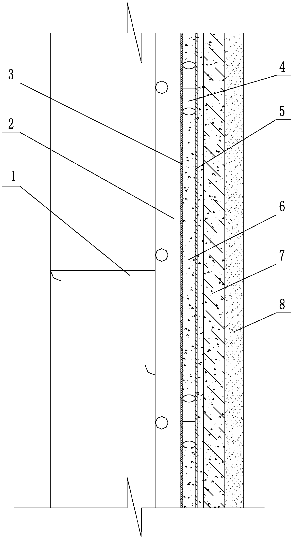
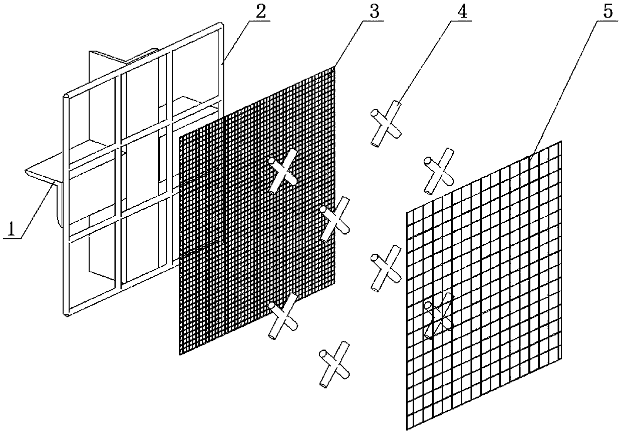
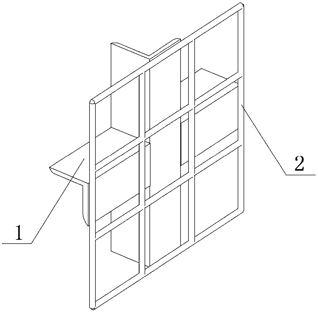
[0035] Please refer to figure 1 with figure 2 , figure 1 A schematic cross-sectional structure diagram of a specific embodiment of the plastic stone molding reinforcement layer provided by the present invention; figure 2...


PUM

PropertyMeasurementUnit
diameteraaaaaaaaaa
thicknessaaaaaaaaaa
lengthaaaaaaaaaa

Abstract

The invention discloses a plastic-stone modeled reinforcing layer, comprising a frame, a bottom reinforcing bar net, a bottom lining net, supports among nets, an upper steel wire net, a mortar base layer, an anti-crack mortar layer and a mortar surface layer which are sequentially arranged, wherein the bottom reinforcing bar net is made from bottom reinforcing bars arranged in a square grid shape and fixed in the frame; the pore diameter of the nets of the bottom lining net is 5mm, and the bottom lining net is fixed in the crossing parts of the bottom reinforcing bars; the supports among nets are distributed at an interval correspondingly to the crossing parts of the bottom reinforcing bars and fixed in the crossing parts of the bottom reinforcing bars; the pore diameter of the nets of the upper steel wire net is 15mm, and the upper steel wire net is fixed on the supports among nets; the space between the bottom lining net and the upper steel wire net is filled with the mortar base layer, and the upper steel wire net is covered by the mortar base layer; the anti-crack mortar layer contains glass fibers and is smeared on the mortar base layer; and the mortar surface layer takes fine sand as an aggregate, and is smeared on the anti-crack mortar layer.

Description

technical field [0001] The invention relates to the technical field of plastic stone molding, in particular to a plastic stone molding reinforcement layer. The invention also relates to a construction method of plastic stone modeling reinforcement layer. Background technique [0002] Plastic stone modeling is mainly used for special modeling construction in garden landscape engineering. Usually, the steel frame is used as the main frame, the single-layer two-way steel mesh is used as the auxiliary frame, and a layer of steel wire mesh is used as the surface mesh, and then on the mesh For plastering and decorative surface treatment. During the construction process, the steel wire mesh is directly plastered. Since the steel wire mesh is in a suspended state, the mortar will fall from the back of the mesh, which not only reduces the material utilization rate, but also affects the grip force of the plastering layer on the surface mesh. Reduce structural strength. [0003] Whe...

Claims


Application Information

Patent Timeline
Patent Type & Authority Applications(China)
IPC IPC(8): B32B13/14B32B15/02B44C5/06
CPCB32B13/14B32B15/02B44C5/06
Inventor 裴旭赵宇阔王会超徐廷博高平华
Owner CHINA CONSTR SIXTH ENG DIV CORP
Why Eureka
Try Eureka