Conveyer

A technology of transmission device and transmission device, which is applied in the direction of conveyors, conveyor objects, transportation and packaging, etc. It can solve the problems that impurities cannot be adsorbed again, inconvenient transportation, machine damage, etc., and it is convenient and effective to move the equipment and fix the base Heat dissipation and transportation, avoiding the effect of adsorption saturation

Inactive Publication Date: 2016-05-04
SHENGZHOU YIHAI MOTOR PARTS FACTORY
View PDF0 Cites 6 Cited by
  • Summary
  • Abstract
  • Description
  • Claims
  • Application Information

AI Technical Summary

Problems solved by technology

If the wire and cable plastic particles cut into granules by a high-speed granulator are directly output from the barrel and packaged, there will undoubtedly be quality problems
In particular, plastic particles are only mixed with magnetic substances. If these foreign objects are not removed, the quality will be affected. In addition, plastic particles generally need to be cleaned before entering the machine. The impurities mixed in these raw materials will cause greater damage to the machine on the one hand, especially Metal impurities such as copper and iron will cause great damage to the transmission and extrusion parts of the machine
At present, the iron scrap removal devices in the industry generally use magnets to clean plastic particles and absorb the ferromagnetic metals that exist in them. However, due to a large amount of plastic passing through, the accumulation is mixed, and it is easy to cause incomplete removal; If the adsorbed metal is not cleaned in time, it is easy to cause the impurities in the plastic raw materials behind to be unable to be adsorbed again, reducing the cleaning effect. Secondly, the existing transmission devices are fixed in a certain position. When it needs to be moved, the handling is very inconvenient and increases the labor intensity.

Method used


Image

  • Conveyer
  • Conveyer
  • Conveyer

Examples


Embodiment Construction

[0020] The preferred embodiments of the present invention will be described in further detail in conjunction with the accompanying drawings.

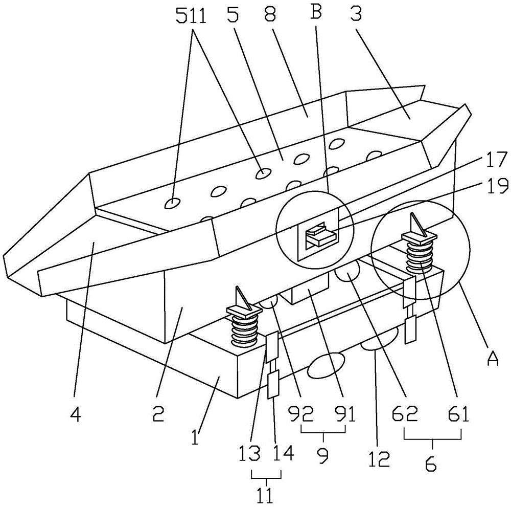
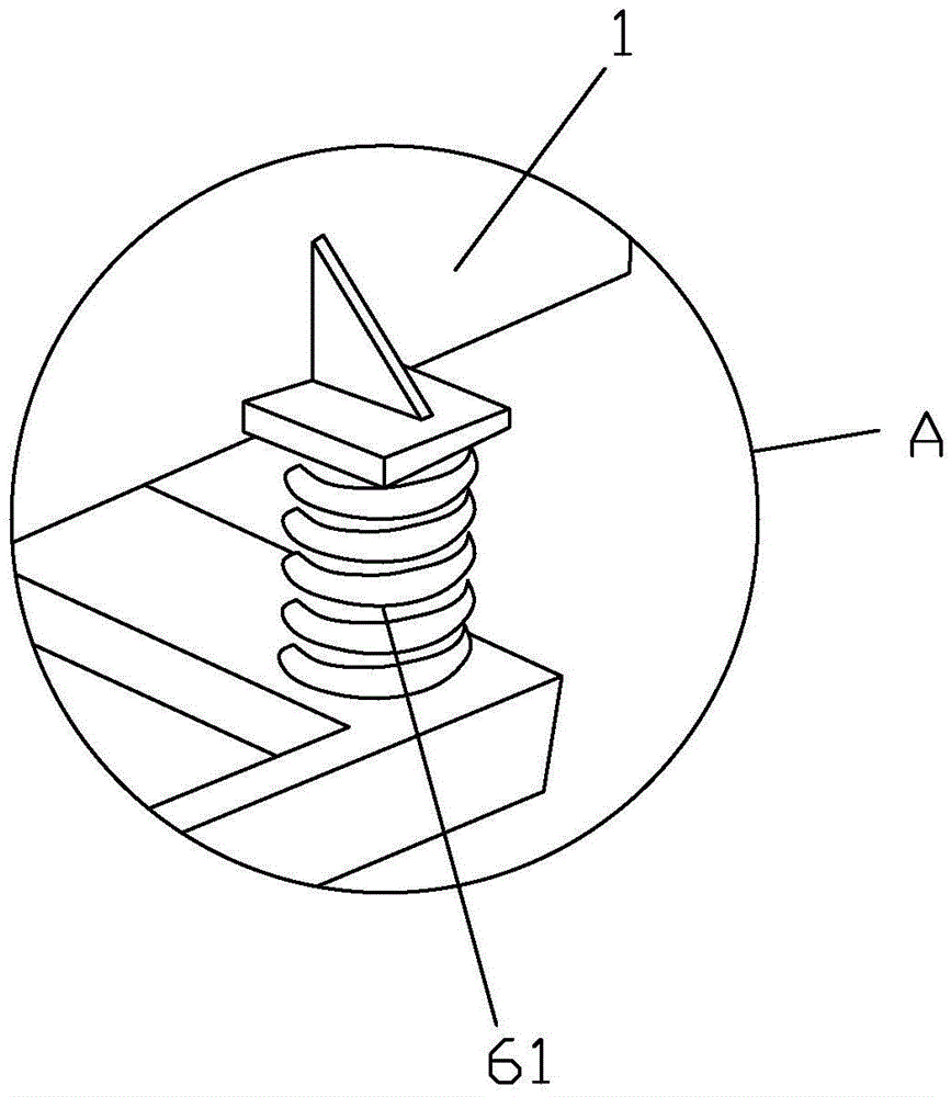
[0021] Such as Figure 1-5 The conveying device includes a base 1 , a support frame 2 , a material inlet 3 , a material outlet 4 , a transmission device 5 and a vibrating device 6 . The support frame 2 is located above the base 1, and the vibration device 6 is located between the support frame 2 and the base 1. The vibration device 6 is composed of a vibration motor 62 and four vibration springs 61, and one end of the vibration springs 61 is respectively connected to On the four corners of the base 1, the other end of the vibration spring 61 is connected to the support frame 2, and the vibration motor 62 drives the support frame 2 to vibrate, thereby driving the plastic particles on the conveyor belt 51 to vibrate, so that the plastic particles are completely shaken away. , disperse, and fully contact with the magnetic stone 511, the i...


PUM


Abstract

The invention discloses a conveyer. The conveyer adopts the technical scheme that the conveyer comprises a base, a supporting frame, a feed opening, a discharge opening and a transmission device, wherein the feed opening and the discharge opening are respectively formed in the two ends of the supporting frame, the transmission device is positioned between the feed opening and the discharge opening, the transmission device comprises a conveying belt, a motor and at least two convey shafts, the motor is arranged inside the supporting frame, the convey shafts are in through connection with the two sides of the interior of the supporting frame, the motor is connected with one of the convey shafts through a chain, the conveying belt is arranged on the convey shaft in a circling manner, at least ten magnetic stones are arranged on the conveying belt and evenly distributed on the conveying belt, a cleaning mechanism below the conveying belt is positioned on the supporting frame, four adjusting devices and four caster wheels are arranged on the lower side of the base, and a refrigeration device is arranged below the supporting frame. The conveyer provided by the invention has the advantages that the structure is simple, the design is reasonable, the cleaning effect is good, the work efficiency is high, and the conveyer can dissipate heat effectively and is convenient to carry.

Description

technical field [0001] The invention relates to the technical field of conveying, in particular to a cable plastic particle conveying device. Background technique [0002] Wire and cable plastic particles are extruded by a screw extruder and cut into pellets by a rotary high-speed pelletizing knife. If the wire and cable plastic particles cut into pellets by a high-speed pelletizing knife are directly output from the barrel and packed, there will undoubtedly be quality problems. In particular, plastic particles are only mixed with magnetic substances. If these foreign objects are not removed, the quality will be affected. In addition, plastic particles generally need to be cleaned before entering the machine. The impurities mixed in these raw materials will cause greater damage to the machine on the one hand, especially Metal impurities such as copper and iron will cause great damage to the transmission and extrusion parts of the machine. At present, the iron scrap removal...

Claims


Application Information

Patent Timeline
Patent Type & Authority Applications(China)
IPC IPC(8): B65G41/00B65G69/04B03C1/18B08B1/02F25B41/00F25B41/40
CPCF25B41/00B65G41/003B65G69/04B03C1/18B08B1/002B08B1/02B65G2201/042
Inventor 陈意
Owner SHENGZHOU YIHAI MOTOR PARTS FACTORY
Why Eureka
Try Eureka