Separation tank for oil-containing waste water

A separation tank and wastewater technology, applied in water/sewage treatment, water/sewage multi-stage treatment, water/sludge/sewage treatment, etc., can solve the problems of poor separation effect, difficult separation and difficult separation of oil substances.

Inactive Publication Date: 2016-05-04
YIBIN GRACE
View PDF5 Cites 3 Cited by
  • Summary
  • Abstract
  • Description
  • Claims
  • Application Information

AI Technical Summary

Problems solved by technology

② The dispersed particle size of the oil in the wastewater is very small, and it is in an emulsified state, so it is not easy to separate from the wastewater
③A small part of the oil is in a dissolved state, making it difficult to separate
The oil trap can only separate larger particles of oily substances, which leads to poor separation effect of oily substances in oily wastewater, and cannot effectively remove oily substances in oily wastewater.
In addition, in the existing technology represented by the above patent documents, in the actual separation process, since the oily substance and the separated wastewater flow in the same direction, the oily substance is easily discharged together with the wastewater, which in turn affects the separation effect

Method used


Image

  • Separation tank for oil-containing waste water
  • Separation tank for oil-containing waste water
  • Separation tank for oil-containing waste water

Examples


Embodiment 1

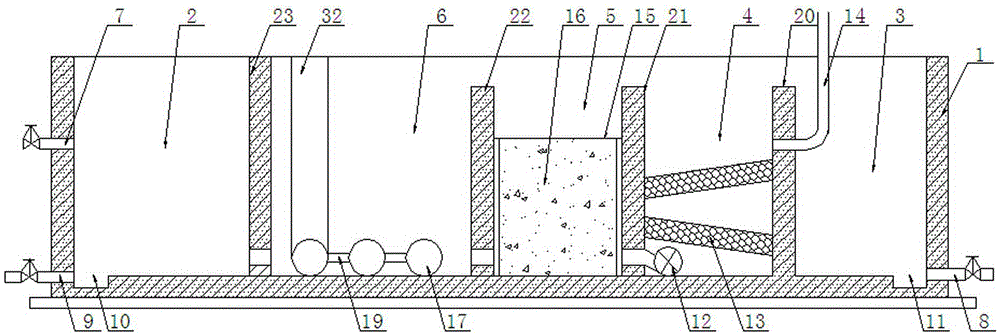
[0028] An oily waste water separation tank, comprising a rectangular pool body 1, four blocks are fixedly arranged in the pool body 1 for sequentially dividing the pool body 1 into an oil discharge chamber 3, a primary separation chamber 4, a secondary separation chamber 5, The partition wall of the third-stage separation chamber 6 and the drainage chamber 2, the bottom of the oil discharge chamber 3 is provided with an oil discharge port 8, and the oil discharge chamber 3 communicates with the upper part of the primary separation chamber 4; the primary separation chamber 4 A submersible pump 12, an activated carbon adsorption layer and a water inlet pipe 14 are arranged inside, the submersible pump 12 is arranged at the lower part of the primary separation chamber 4, and the water outlet end of the submersible pump 12 is located at the lower part of the secondary separation chamber 5, and the water inlet pipe 14 Set above the submersible pump 12, the activated carbon adsorptio...

Embodiment 2

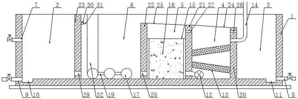
[0037] An oily waste water separation tank, comprising a rectangular pool body 1, four blocks are fixedly arranged in the pool body 1 for sequentially dividing the pool body 1 into an oil discharge chamber 3, a primary separation chamber 4, a secondary separation chamber 5, The partition wall of the third-stage separation chamber 6 and the drainage chamber 2, the bottom of the oil discharge chamber 3 is provided with an oil discharge port 8, and the oil discharge chamber 3 communicates with the upper part of the primary separation chamber 4; the primary separation chamber 4 A submersible pump 12, an activated carbon adsorption layer and a water inlet pipe 14 are arranged inside, the submersible pump 12 is arranged at the lower part of the primary separation chamber 4, and the water outlet end of the submersible pump 12 is located at the lower part of the secondary separation chamber 5, and the water inlet pipe 14 Set above the submersible pump 12, the activated carbon adsorptio...


PUM


Abstract

The invention discloses a separation tank for oil-containing waste water. The separation tank comprises a tank body; four partition walls are fixedly arranged in the tank to successively divide the tank body into an oil discharging chamber, a primary separation chamber, a secondary separation chamber, a ternary separation chamber and a water draining chamber; an oil discharging outlet is arranged at the lower part of the oil discharging chamber; the oil discharging chamber is communicated with the upper part of the primary separation chamber; a submersible pump, an active carbon adsorption layer and a water inlet pipe are arranged in the primary separation chamber; a coarse graining accommodation chamber is arranged in the secondary separation chamber and filled with a coarse grained filling material; the lower part of the ternary separation chamber is provided with a perforating pipe; the perforating pipe is connected with an aerator arranged out of the ternary separation chamber; the ternary separation chamber is communicated with the lower part of the water draining chamber; the lower part of the water draining chamber is provided with a sewage draining outlet; and the central part of the water draining chamber is provided with a water outlet. The separation tank provided by the invention can separate oily substances in oil-containing waste water in a counter-current flowing manner and successively separate the oily substances according to the particle sizes of the oily substances in a sequence from large-particle-size substance to small-particle-size substance.

Description

technical field [0001] The invention belongs to the field of wastewater treatment equipment, in particular to an oily wastewater separation tank. Background technique [0002] Petroleum industry, mechanical processing industry and catering industry discharge a large amount of oily wastewater in the production process. If the oily wastewater is not recycled, it will cause waste; if it is discharged into rivers, lakes or bays, it will pollute the water body and affect the survival of aquatic organisms; Agricultural irrigation will block the soil voids and hinder the growth of crops. Therefore, oily wastewater must be recycled, not only to avoid environmental pollution, but also to obtain considerable economic benefits. [0003] In the prior art, a grease trap is usually used to separate oily wastewater. The grease trap is a structure that uses the difference in specific gravity between oil and water to separate and remove suspended oil with large particles in wastewater. For...

Claims


Application Information

Patent Timeline
Patent Type & Authority Applications(China)
IPC IPC(8): C02F9/02
CPCC02F1/283C02F1/40C02F9/00
Inventor 张杨瞿继丹郝军
Owner YIBIN GRACE
Why Eureka
Try Eureka