
Assembled cable saddle structure for suspension bridge

A technology of assembled and suspension bridges, applied in the directions of suspension bridges, bridge forms, bridges, etc., can solve the problems of large transportation and hoisting difficulties, single block volume, large weight, difficult control of mechanical processing, etc., and achieves low requirements for transportation and hoisting equipment. , Simple processing, flexible assembly effect

Active Publication Date: 2016-05-04
ZHEJIANG PROVINCIAL INST OF COMM PLANNING DESIGN & RES CO LTD
View PDF6 Cites 17 Cited by
  • Summary
  • Abstract
  • Description
  • Claims
  • Application Information

AI Technical Summary

Problems solved by technology

The full-cast cable saddle is a casting that casts the saddle groove and the lower seat body as a whole. After heat treatment and machining, the manufacturing process is relatively simple, but the weight is relatively large, and it is difficult to control the later machining, and the casting is easy. Various casting defects
The fully welded cable saddle is welded by various steel plates, its weight is relatively small, and the amount of steel used is less, but the welding process is too complicated. Currently, only a few bridges use this type of saddle
The cast-welded cable saddle means that the saddle groove part is made of casting, and the lower seat is made of thick steel plate, which is connected into a whole by welding after being aligned with each other. It has the advantages of both full-cast and fully-welded saddles However, it needs to be welded and assembled in the factory. The volume and weight of a single block are still relatively large, and there are great difficulties in transportation and hoisting, especially in mountainous environments with poor transportation conditions.

Method used


Image

  • Assembled cable saddle structure for suspension bridge
  • Assembled cable saddle structure for suspension bridge
  • Assembled cable saddle structure for suspension bridge

Examples


Embodiment 1

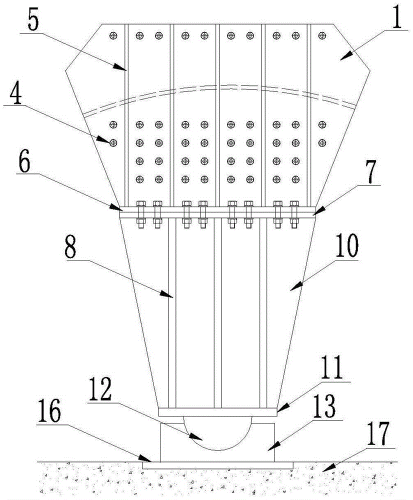
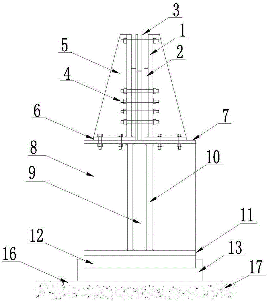
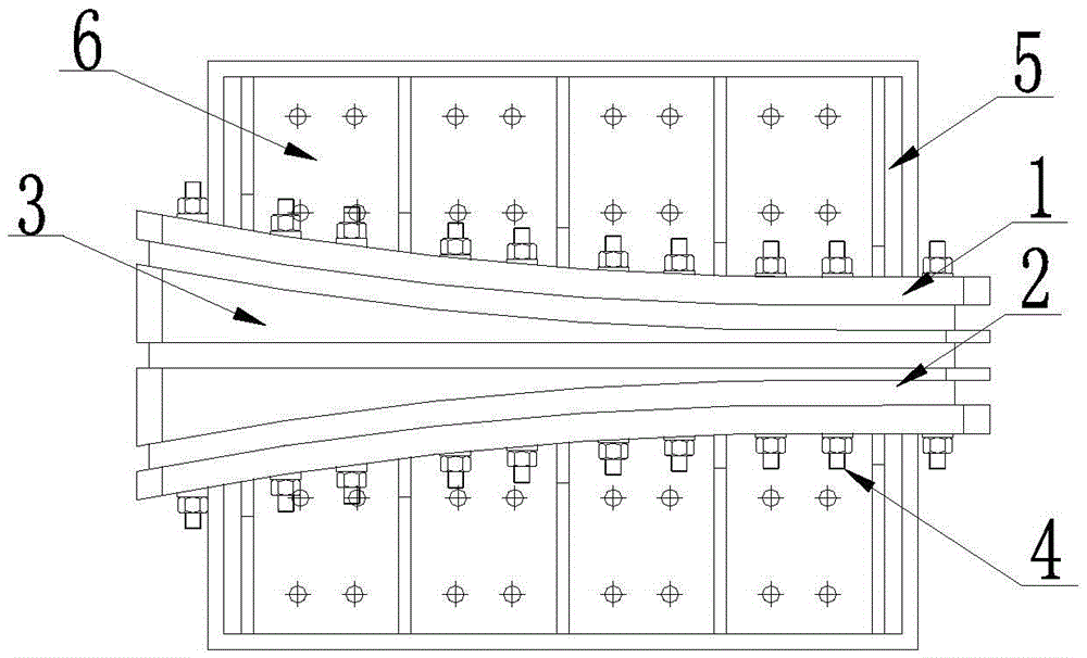
[0034] Such as Figure 1 ~ Figure 3 As shown in the figure, a new type of loose cable saddle structure is formed by welding the side plate 1 and the transverse rib plate 5 to form a side plate, which is connected with the saddle support plate 2 and the partition plate 3 through high-strength bolts 4 to form a saddle groove. The parts are processed and formed according to the requirements, wherein the partition becomes thicker in the longitudinal direction, the side plate is tightly connected to the saddle bottom plate 6 and the transverse rib 5 is welded to the saddle bottom plate to enhance the stability of the steel plate. Bolting or welding is used to connect the groove base 13 to the foundation backing plate 16, so as to achieve consolidation with the foundation 17, and the upper bearing plate 7, the longitudinal plate 10, the middle transverse plate 9, the side transverse plate 8, and the lower base plate are welded. 11 and the rotating shaft 12 are connected into one bod...

Embodiment 2

[0036] Such as Figure 4 As shown in Fig. 1, another new type of loose cable saddle structure is formed by welding the side plate 1 and the transverse rib plate 5 to form a side plate, which is connected with the saddle support plate and the partition plate through high-strength bolts 4 to form a saddle groove. It is processed and formed according to the requirements, wherein the partition plate becomes thicker in the longitudinal direction, the side plate and the saddle bottom plate 6 are tightly pressed and the transverse rib 5 is welded to the saddle bottom plate to enhance the stability of the steel plate. The upper support plate 7, the longitudinal plate 10, the middle transverse plate, the side transverse plate 8, and the lower base plate 11 are welded to form a seat body, and a sliding shaft 14 is arranged between the lower base plate 11 of the seat body and the foundation backing plate 16 to realize the seat body. For longitudinal displacement requirements, the sliding...

Embodiment 3

[0038] Such as Figure 5 ~ Figure 7As shown, a new assembled main cable saddle structure, the side plate is welded by the side plate 1 and the transverse rib plate 5 and connected with the saddle support plate 2 and the partition plate 3 through high-strength bolts 4 to form a saddle groove, the partition plate The thickness is equal in the longitudinal direction, the side plate is pressed against the saddle bottom plate 6 and the transverse rib 5 is welded to the saddle bottom plate to enhance the stability of the steel plate. The upper bearing plate 7, the longitudinal plate 10, the middle horizontal plate 9, the side horizontal plate 8, and the lower bottom plate 11 are connected into a seat body by welding, and a pushing sliding friction pair 19 is set between the lower bottom plate 11 of the seat body and the foundation backing plate 16, In order to realize the deviation requirement of the saddle during the construction stage, after the work of pushing the saddle is compl...


PUM


Abstract

The invention discloses an assembled cable saddle structure for a suspension bridge, which is composed of an upper part and a lower part, wherein the upper part is assembled into a saddle groove of a main cable saddle or a vice cable saddle by connecting and welding steel plates in various specifications through high-strength bolts, and the lower part is assembled into a bearing bracket of the main cable saddle or the vice cable saddle by welding the steel plates; the upper part is connected with the lower part through high-strength bolts or welded seams; and the bearing bracket can be in running fit, sliding fit or stationary fit with a base. Compared with the traditional casting or cast-weld combined saddle, the assembled cable saddle structure disclosed by the invention has the advantages of simpler processing, more convenient transportation, more flexible assembly and more reliable quality, can serve as the saddle of the suspension bridge, and is especially suitable for a large-span suspension bridge in a mountainous area with difficult transportation conditions.

Description

technical field [0001] The invention belongs to the technical field of cable saddle structures for suspension bridges, and in particular relates to an assembled cable saddle structure for suspension bridges. Background technique [0002] Suspension bridges use main cables and slings as the suspension system of stiffened beams to transfer loads to bridge towers and anchorage bridges. The main load-bearing structure of the bridge is composed of bridge towers and high-strength flexible cables suspended on the bridge towers. It is composed of sling, stiffening beam and anchor structure. The loads on the spans are carried by the stiffening beams and transferred to the cables by the hangers. The main cables are the main load-bearing structure, but they are only in tension. The cable itself is a geometrically variable body, but it can form a balanced force-bearing structural system with a certain geometric shape in space through the combination of bridge towers, anchorage structu...

Claims


Application Information

Patent Timeline
IPC IPC(8): E01D19/14E01D11/02
CPCE01D11/02E01D19/14
Inventor 王昌将叶雨清王路王晓阳戴显荣马越峰
Owner ZHEJIANG PROVINCIAL INST OF COMM PLANNING DESIGN & RES CO LTD
Learn More