Wall used in building

A technology for construction and walls, applied in the direction of buildings, building components, building structures, etc., can solve the problems of waterproof, moisture-proof, large manpower demand, poor thermal insulation and sound insulation, etc., and achieve good dryness and thermal insulation performance. The effect of reducing the demand for manpower and improving the load-bearing capacity

Active Publication Date: 2016-05-04
南京市第二建筑设计院有限公司
View PDF7 Cites 5 Cited by
  • Summary
  • Abstract
  • Description
  • Claims
  • Application Information

AI Technical Summary

Problems solved by technology

[0002] As the country vigorously promotes urbanization, the demand for buildings is increasing year by year. In traditional buildings, the walls are made of bricks manually by construction workers. This construction method has a long cycle and a large demand for manpower. The cost is very high, and the walls of traditional buildings are all single-layer bricks such as earth bricks or cement bricks. This kind of building structure has poor sound insulation, waterproof, moisture-proof and other functions, and cannot meet the requirements of modern people for houses.
[0003] In recent years, templated buildings have gradually been introduced into the construction of some simple factory buildings or sheds. The walls used in this modular building are made of light-weight materials. Generally, only 1-2 floors are built for thermal insulation and sound insulation. The property is very poor, and the structure is not solid, and the safety is not high, so there is an urgent need for a wall that can be applied to the construction of high-rise buildings.

Method used


Image

  • Wall used in building
  • Wall used in building
  • Wall used in building

Examples


Embodiment Construction

[0026] The preferred embodiments of the present invention will be described in detail below in conjunction with the accompanying drawings, so that the advantages and features of the present invention can be more easily understood by those skilled in the art, so as to define the protection scope of the present invention more clearly.

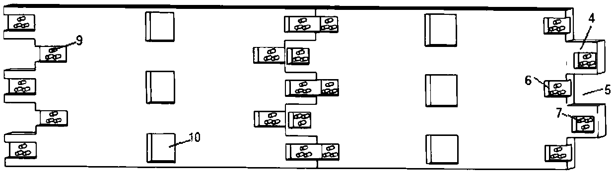
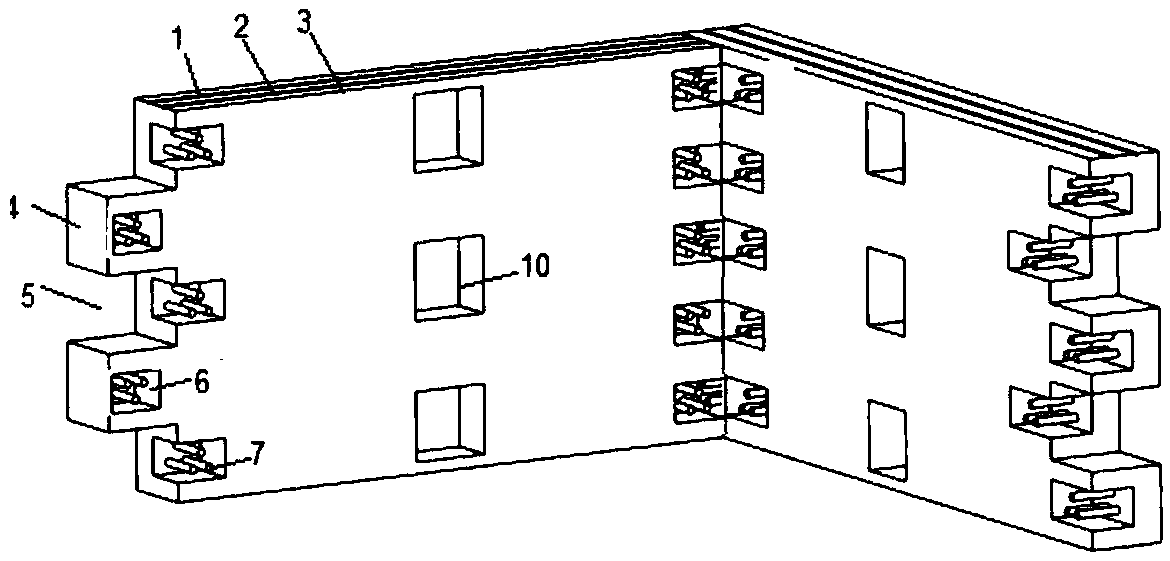
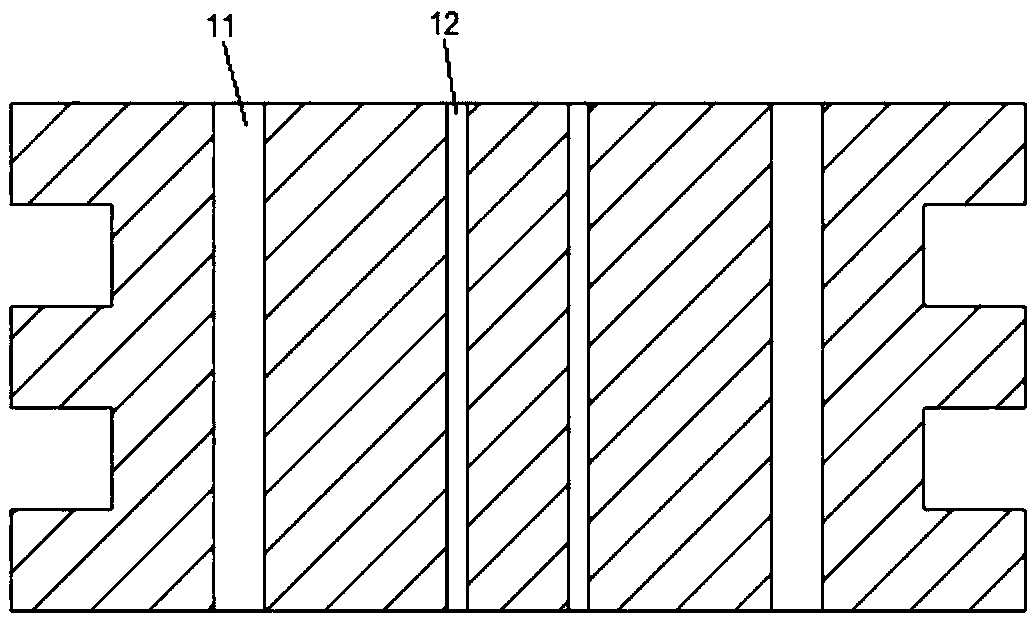
[0027] like Figure 1-3 As shown, the building wall of an embodiment of the present invention includes a plurality of wall panels, and the wall panels are composed of an outer wall panel 1, an insulation layer 2 and an inner wall panel 3; the end faces Y on both sides of the wall panels There are protrusions 4 and grooves I5 with matching shapes at intervals in the direction, and the wall panels are connected in parallel or vertically through matching protrusions 4 and grooves I5 to form a plane wall or a wall with a right angle; The surface of the side is provided with a groove Ⅱ6, and the connecting rod 7 that runs through the wallboard at the ...


PUM


Abstract

The invention discloses a wall used in a building. The wall comprises a plurality of wallboards. The wallboard is formed by an outer layer wallboard, a heat-insulation layer and an inner layer wallboard. two side end faces of the wallboard are respectively provided with bulges and grooves I at interval in Y direction, the shapes of the bulges and grooves I being matched. The wallboards are connected in a parallel or vertical manner. The surfaces of two sides of the wallboard are provided with grooves II. The groove II is internally provided with a connecting rod passing through the wallboard in advance. The corresponding connecting rod in the grooves II of the connected wallboard is fixed or movably connected through a connecting plate. The grooves II are internally filled with materials. The grooves II are internally provided with a plurality of connecting rods in advance. Two ends of the connecting plate are respectively provided with holes corresponding to the number and positions of the connecting rods. The connecting rod passes through the hole in the connecting plate, so that the connecting plate is embedded in the groove II. The connecting plate is a straight plate-like metal piece or an angle iron. The wall used in a building is firm in structure, good in compressive resistance, simple in construction, short in construction period, good in heat insulation and sound insulation, low in cost, very convenient in assembly, and high in security.

Description

technical field [0001] The invention relates to the field of architectural design, in particular to a building wall. Background technique [0002] As the country vigorously promotes urbanization, the demand for buildings is increasing year by year. In traditional buildings, the walls are made of bricks manually by construction workers. This construction method has a long cycle and a large demand for manpower. The cost is very high, and the walls of traditional buildings are single-layer bricks such as earth bricks or cement bricks. This kind of building structure has poor sound insulation, waterproof, moisture-proof and other functions, and cannot meet the requirements of modern people for houses. [0003] In recent years, templated buildings have been slowly introduced into the construction of some simple factory buildings or sheds. The walls used in this modular building are made of light-weight materials. Generally, only 1-2 floors are built for thermal insulation and sou...

Claims


Application Information

Patent Timeline
IPC IPC(8): E04B2/00E04B1/76E04B1/61
CPCE04B1/6125E04B1/76E04B2/00
Inventor 王盈胡忆南彭小青
Owner 南京市第二建筑设计院有限公司
Why Eureka
Try Eureka