
Roller oscillating tooth gear reducer

A technology of movable tooth reducer and roller, which is applied in the direction of gear transmission, belt/chain/gear, transmission parts, etc., which can solve the problems of short service life and achieve long service life, improved accuracy and high rotation precision. Effect

Inactive Publication Date: 2016-05-04
秦皇岛博硕光电设备股份有限公司
View PDF6 Cites 4 Cited by
  • Summary
  • Abstract
  • Description
  • Claims
  • Application Information

AI Technical Summary

Problems solved by technology

[0003] The purpose of the present invention is to provide a transmission with a long service life and high torque capacity for the short service life and the need for regular replacement when the prior art reducer is used for a solar azimuth tracker

Method used


Image

  • Roller oscillating tooth gear reducer
  • Roller oscillating tooth gear reducer

Examples


Embodiment Construction

[0015] Below in conjunction with accompanying drawing and embodiment the present invention will be further described:

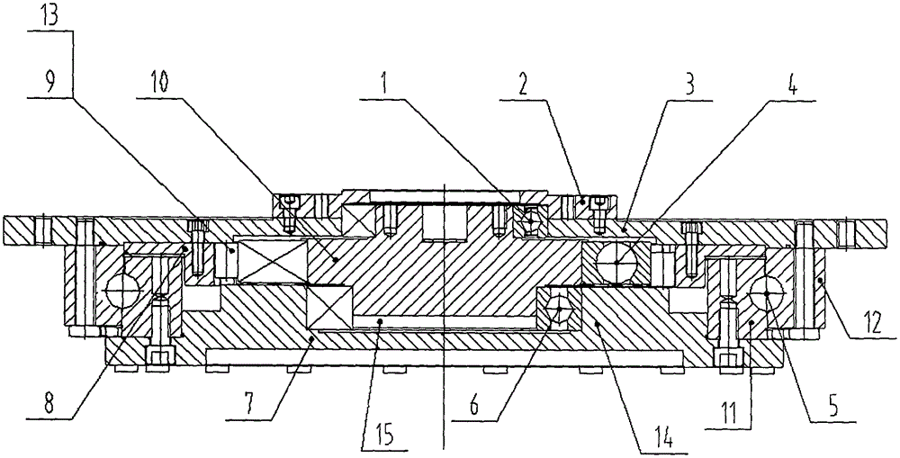
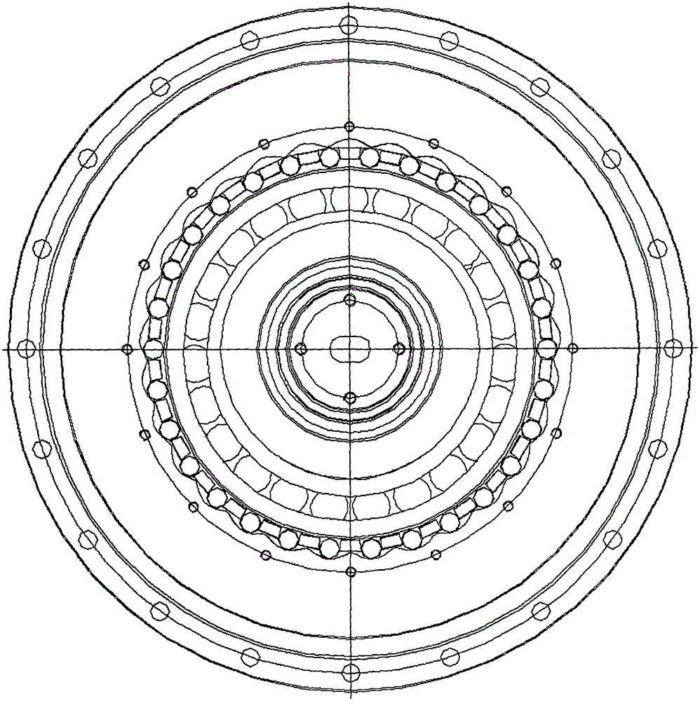
[0016] Such as figure 2 combine figure 1 As shown, the reducer of the present invention is a roller movable gear reducer, which includes an input shaft 10, an output shaft 7, a housing 8, cylindrical rollers 9 and a front end cover 3. The input shaft 10 is provided with an eccentric shaft section and a support section 1 and a support section 2, and the support section 1 and the support section 2 are respectively arranged on both sides of the eccentric shaft section; one end of the output shaft 7 is a connecting end, which is connected with the load, and the other end is The mating end is provided with an annular protrusion 14 and a mating hole 15, and a hobbing groove 13 is arranged on the annular protrusion, and the hobbing groove is arranged on the end face of the mating end of the output shaft 7 at intervals along the circumference. The annular protrusi...


PUM


Abstract

The invention provides a roller oscillating tooth gear reducer to solve the defect that a speed reducer in the prior art is short in service life and needs periodic replacement when used for a solar energy azimuth tracker. The roller oscillating tooth gear reducer comprises an input shaft, an output shaft, a housing, a cylindrical roller, and a front end cover, wherein the input shaft is rotationally connected with the front end cover; the roller oscillating tooth gear reducer further comprises a slewing bearing; the front end cover is fixedly connected with an outer ring of the slewing bearing; the output shaft is fixedly connected with an inner ring of the slewing bearing. The roller oscillating tooth gear reducer with the structure is adopted to track the solar energy azimuth; the roller oscillating tooth gear reducer adopts multi-teeth engagement transmission, so that the torque on the reducer can be dispersed to a plurality of teeth, the torque on each tooth is greatly reduced, and the service life of the reducer is prolonged; the slewing precision of the output shaft is high, accurate responses can be given to received azimuth signals, and the accuracy of a solar panel tracking the sun orbit can be remarkably improved.

Description

technical field [0001] The invention belongs to the technical field of reducers, in particular to a roller movable tooth reducer. Background technique [0002] At present, the reducer used in the solar azimuth tracker is a rotary reducer, which is composed of a worm driven by a worm gear, and is driven by mutual meshing between teeth. The use of the above-mentioned structure reducer on the solar azimuth tracker has the following disadvantages: Since the solar tracker is installed outdoors, it is subjected to various loads caused by wind, snow, and self-weight during work, and the load size is uncertain. The large change in torque makes the teeth of the worm gear easily damaged, making the service life of the reducer low. According to statistics, the reducer works under this working condition, and its average service life is 3-5 years. If it is not replaced in time, The solar tracker is not working properly. Therefore, very high requirements are put forward for the use and ...

Claims


Application Information

Patent Timeline
Patent Type & Authority Applications(China)
IPC IPC(8): F16H1/32F16H57/021
CPCF16H1/2809F16H1/32F16H57/021
Inventor 路百超姜向赟张杰褚凌越
Owner 秦皇岛博硕光电设备股份有限公司
Learn More