Anti-blocking self-vibrating ring for sprayed concrete pumping pipe

A shotcrete and pumping pipe technology, which is applied in the direction of pipe components, pipes/pipe joints/pipes, mechanical equipment, etc. The effect of mitigating the impact of impact

Active Publication Date: 2016-05-04
XIAN UNIV OF SCI & TECH
View PDF6 Cites 6 Cited by
  • Summary
  • Abstract
  • Description
  • Claims
  • Application Information

AI Technical Summary

Problems solved by technology

[0003] The purpose of the present invention is to solve the problem that the sprayed concrete pumping pipe is prone to blockage or even burst, and to provide a self-vibrating ring for preventing the blockage of the sprayed concrete pumping pipe

Method used


Image

  • Anti-blocking self-vibrating ring for sprayed concrete pumping pipe
  • Anti-blocking self-vibrating ring for sprayed concrete pumping pipe
  • Anti-blocking self-vibrating ring for sprayed concrete pumping pipe

Examples


Embodiment 1

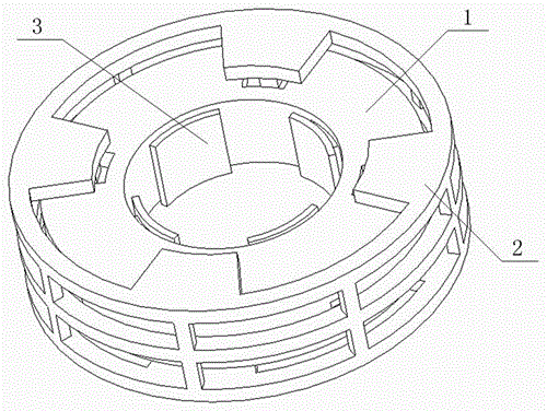
[0033] A shotcrete pumping pipe anti-blocking self-vibration ring, such as figure 1 As shown, it includes a vibrating ring 1, an annular support 2 sleeved outside the vibrating ring 1, and a pressure detection device 3 embedded in the vibrating ring 1;

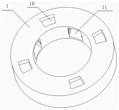
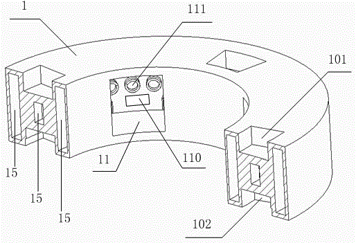
[0034] Among them, such as figure 2 with image 3 As shown, the upper surface and the lower surface of the vibrating ring 1 are respectively provided with corresponding grooves 10, the grooves 10 include a group of upper grooves 101 uniformly arranged on the upper surface, and the positions corresponding to the upper grooves 101 in the lower surface A group of lower grooves 102 with the same specifications as the upper grooves 101 are set;

[0035] In the middle of the upper groove 101 and the lower groove 102, as well as on the radially front surface and the rear surface, and the vibrating ring 1 that is located in the corresponding position, a magnetic levitation electromagnet 15 is arranged inside; the upper groove 101 a...

Embodiment 2

[0045] On the basis of embodiment 1, the distribution of the magnetic levitation electromagnet 15 around the upper groove 101 and the lower groove 102 can also be as follows Figure 4 Shown: the middle of the upper groove 101 and the lower groove 102, and the radial front surface and the rear surface and are located in the vibrating ring 1 in the corresponding position. A magnetic levitation electromagnet 15 is arranged inside; the upper groove 101 and the lower groove 102 Insulation baffles 104 are connected to the sidewalls on both sides of the interior along the circumferential direction through buffer springs 103 .

Embodiment 3

[0047] On the basis of embodiment 1, the corresponding two pressure sensors 16 in the vibration automatic adjustment circuit in the magnetic levitation and vibration automatic adjustment circuit II can also be connected to a microcontroller 13 at the same time, and this microcontroller 13 is connected with the The two pressure sensors 16 correspond to the vibrator 14 .

[0048] Working principle of the present invention: the present invention is controlled by two sets of circuits including power on and off and pressure applying circuit I and magnetic levitation and vibration automatic adjustment circuit II, which can realize automatic control of its vibration and stillness, pressure and relaxation, and can automatically control according to the pressure. The vibration frequency and amplitude can be adjusted, and magnetic levitation can be realized in the pipe diameter and along the pipe length, so that the impact of the vibration ring 2 on the outer pipe can be minimized, so th...


PUM


Abstract

The invention discloses an anti-blocking self-vibrating ring for a sprayed concrete pumping pipe. A groove is formed in the vibrating ring; a vibrator is mounted on the inner part of the vibrating ring; a pressure slot is arranged on the inner wall of the vibrating ring; a magnetic suspension electromagnet is mounted at the periphery of the groove; a fan-shaped frame is arranged on a ring-shaped bracket; a bulge is arranged on the fan-shaped frame; the magnetic suspension electromagnet is mounted at the periphery of the bulge; the bulge is embedded into the groove; and a pressure detecting device is mounted in the pressure slot. The anti-blocking self-vibrating ring has the function of automatically switching on and switching off, can complete switching among three working states of vibrating, strengthened vibrating, and stopping vibrating according to the blocking pressure of the pipe wall of the sprayed concrete pumping pipe, and also can automatically strength the vibrating frequency and the vibrating amplitude of the vibrating ring along with the increase of pressure, so that the pipe blocking problem of the sprayed concrete pumping pipe is solved, an interior electromagnet system can enable the vibrating ring to realize magnetic suspension in a pipe diameter direction and a pipeline direction, the impact effect of the vibrating ring to the pipeline outer pipe is greatly relieved, and the energy can be utilized to vibrate the sprayed concrete pumping pump to the greatest extent.

Description

technical field [0001] The invention relates to a wet spraying equipment, in particular to an anti-blocking self-vibrating ring of a sprayed concrete pumping pipe, which belongs to the field of building construction. Background technique [0002] At this stage, wet shotcrete technology has significant advantages over traditional spraying methods such as dry spraying or tidal spraying, eliminating the problems of high dust concentration and easy slump of slurry. However, even so, wet shotcrete technology has a certain There are still some deficiencies in these aspects. The main technical difficulty restricting the promotion of wet shotcrete is that the shotcrete pumping pipe is prone to blockage during work, and there is no effective solution now. Nowadays, the most commonly used method at the construction site is to artificially apply external force and other methods to vibrate the sprayed concrete pumping pipe from the outside to achieve the purpose of slowing down the bloc...

Claims


Application Information

Patent Timeline
Patent Type & Authority Applications(China)
IPC IPC(8): F16L55/24
CPCF16L55/24
Inventor 申艳军杨振王思琦
Owner XIAN UNIV OF SCI & TECH
Why Eureka
Try Eureka