Energy saver for vertical natural circulation condensing boiler

A technology of natural circulation and condensing boilers, applied in steam boilers, water tube steam boilers, combustion methods, etc., can solve the problems of large footprint, corrosion, limited recovery effect, etc., to solve the problem of large footprint and reduce manufacturing costs , Solve the effect of excessive steel consumption

Active Publication Date: 2016-05-04
SHANGHAI INDAL BOILER RES INST
View PDF5 Cites 3 Cited by
  • Summary
  • Abstract
  • Description
  • Claims
  • Application Information

AI Technical Summary

Problems solved by technology

[0002] At present, the existing gas-fired boilers are mainly divided into two types: vertical and horizontal. The tail condensing heat exchanger of the horizontal gas-fired boiler has the following disadvantages: the single use of condensation recovery will generate a large amount of condensed water. With the current technology, even if acid-resistant steel or Stainless steel cannot guarantee the service life of the condenser, and the single condensation recovery makes the heat exchanger too bulky and consumes a lot of steel. Since the condensation surface cannot be accurately controlled, the selected materials must use corrosion-resistant materials, which greatly increases the cost.
[0003] At present, the tail economizers of vertical gas boilers have the following disadvantages and deficiencies: the use of conventional tail heat exchangers takes up a large area and consumes a lot of steel. The single use of air preheater recovery has limited recovery effects, large structures, and heat transfer accuracy cannot be achieved. Control, once the flue gas condensation occurs, it will be corroded quickly

Method used


Image

  • Energy saver for vertical natural circulation condensing boiler
  • Energy saver for vertical natural circulation condensing boiler
  • Energy saver for vertical natural circulation condensing boiler

Examples


Embodiment Construction

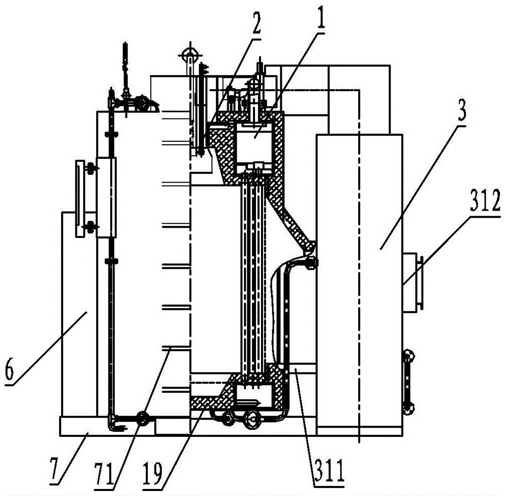
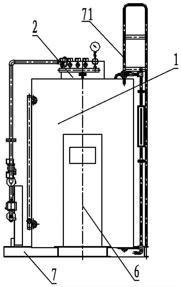
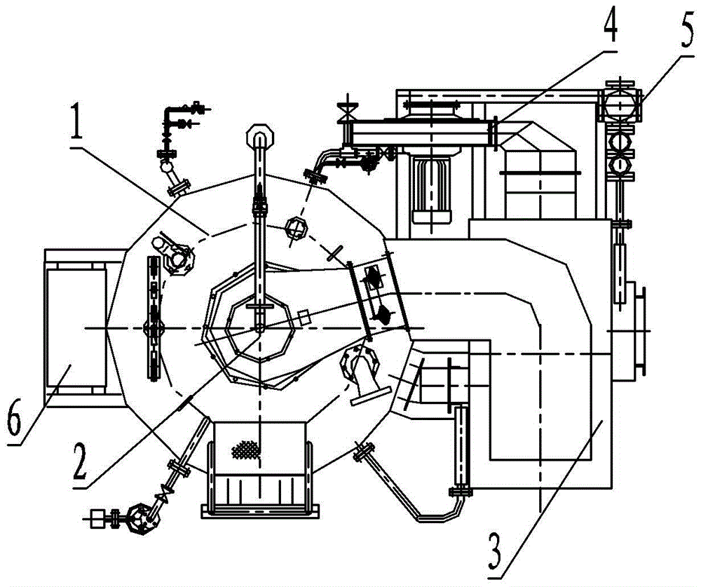
[0029] see figure 1 In order to better understand the technical solution of the present invention, the inventors of the present invention will describe in detail below through specific embodiments in conjunction with the accompanying drawings:

[0030] see figure 1 , a vertical natural circulation condensing boiler of the present invention includes a boiler body 1, and the boiler body 1 is divided into a furnace 11 and a flue gas chamber 12 arranged coaxially. A smoke outlet 13 is provided on the outer peripheral wall of the smoke cavity 12 . The upper and lower ends of the smoke chamber 12 are respectively provided with an upper annular header 16 and a lower annular header 17 . The upper annular header 16 and the lower annular header 17 communicate with each other through a centralized ascending tube bundle 14 and a concentrated descending tube bundle 15 . Among them, the centralized descending pipe bundle 15 is composed of a circle of concentrated descending pipes arrange...


PUM


Abstract

The invention discloses an energy saver for a vertical natural circulation condensing boiler. The energy saver is divided by a smoke baffle into an air heating chamber on the upper side and a smoke cooling chamber on the lower side. The smoke cooling chamber is provided with a smoke discharge opening and a smoke recovery opening. The air heating chamber is provided with an air outlet channel and an air inlet channel. A heat exchanger vertically penetrating through the smoke baffle is arranged at the center of the energy saver. A non-condensate heated face between the smoke recovery opening and the heat exchanger and a condensate heated face between the smoke discharge opening and the heat exchanger are arranged in the smoke cooling chamber. The temperatures of the condensate heated face, the heat exchanger and the non-condensate heated face are gradually increased. The energy saver has the technical advantages that smoke heat is recovered, the air inlet temperature and the water inlet temperature of the boiler are synchronously increased through heating, the defect that only the air inlet temperature of an existing vertical gas boiler is increased through heating is overcome in a breakthrough mode, and manufacturing cost is greatly reduced.

Description

technical field [0001] The invention relates to an economizer for a vertical natural circulation condensing boiler. Background technique [0002] At present, the existing gas-fired boilers are mainly divided into two types: vertical and horizontal. The tail condensing heat exchanger of the horizontal gas-fired boiler has the following disadvantages: the single use of condensation recovery will generate a large amount of condensed water. With the current technology, even if acid-resistant steel or Stainless steel cannot guarantee the service life of the condenser, and the single condensation recovery makes the heat exchanger too bulky and consumes a lot of steel. Since the condensation surface cannot be accurately controlled, the selected materials must use corrosion-resistant materials, which greatly increases the cost. [0003] At present, the tail economizers of vertical gas boilers have the following disadvantages and deficiencies: the use of conventional tail heat exchan...

Claims


Application Information

Patent Timeline
Patent Type & Authority Applications(China)
IPC IPC(8): F22B21/06F22B31/00F22B31/08F23L15/00
CPCF22B21/065F22B31/00F22B31/08F23L15/00Y02E20/34
Inventor 林欣郑伟伟汪杰何心良余安明潘鑫波
Owner SHANGHAI INDAL BOILER RES INST
Why Eureka
Try Eureka