
Structure for testing stress gradient of MEMS micro beam with detection hole, and measurement method

A technology of stress gradient and test structure, which is applied in the measurement of the change force of the optical properties of the material when it is stressed, can solve the problems of off-plane bending, affecting device performance, buckling, etc., and achieve lower requirements and intuitive observation methods , Accurate and reliable measurement results

Active Publication Date: 2016-05-04
SOUTHEAST UNIV
View PDF9 Cites 0 Cited by
  • Summary
  • Abstract
  • Description
  • Claims
  • Application Information

AI Technical Summary

Problems solved by technology

Therefore, during the MEMS process, residual stress will inevitably be generated. When the stress distribution along the thickness direction of the material is non-uniform, that is, there is a stress gradient, the cantilever beam structure or the fixed-supported beam structure fixed at both ends, after the structure is released ( corrode the support sacrificial layer under the beam, so that the beam is suspended), there will be out-of-plane bending or buckling, which directly affects the performance of the device

Method used


Image

  • Structure for testing stress gradient of MEMS micro beam with detection hole, and measurement method

Examples


Embodiment Construction

[0020] The present invention will be further described below in conjunction with the accompanying drawings and specific embodiments.

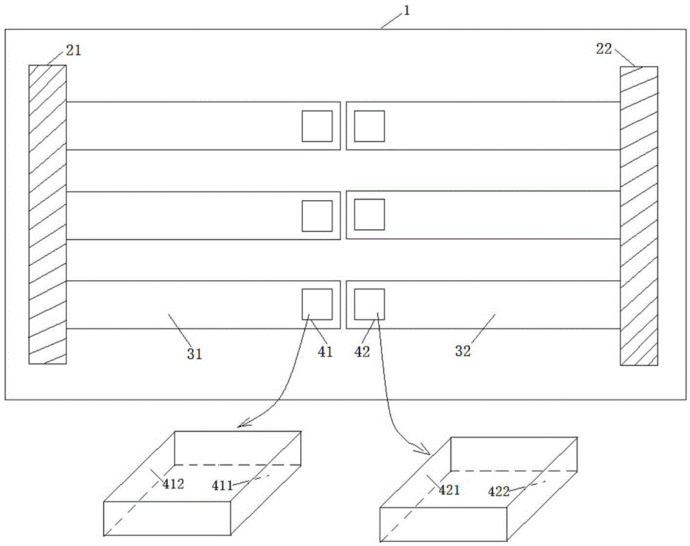
[0021] Such as figure 1 Shown, a kind of test structure of the MEMS microbeam stress gradient that has detection hole, comprises substrate 1, two long anchor regions 21 and 22 and six measured cantilever beams with detection hole;

[0022] The two long anchor regions 21 and 22 are respectively fixed on the upper surface of the substrate 1;

[0023] One end of the tested cantilever beam is fixed on one side of the long anchorage area, and a square through hole is etched near the end of the other end as a detection hole, and the side wall of the detection hole 41 or 42 is perpendicular to the surface;

[0024] The six cantilever beams with detection holes are fixed in groups of three in parallel to each other on the side of a long anchorage area 21 or 22; the suspension ends of the two groups of cantilever beams 31 and 32 to be tested correspond...


PUM


Abstract

The invention discloses a structure for testing the stress gradient of an MEMS micro beam with a detection hole, and a measurement method. The structure comprises a substrate, two long anchor regions, and six tested cantilever beams with detection holes. The two long anchor regions are fixed on the upper surface of the substrate. One end of each tested cantilever beam is fixed on a side surface of the corresponding long anchor region, and the other end of each tested cantilever beam is provided with a square through hole in an etching manner, wherein the square through holes serve as the detection holes, and side wall of the detection holes are perpendicular to the surface. Each three tested cantilever beams serve as a group, and each group of tested cantilever beams are fixed in the corresponding long anchor region. The suspension ends of the two groups of tested cantilever beams are opposite to each other, and are oppositely arranged in a completely symmetric manner. When the tested cantilever beams are bent upwards or downwards because of the stress gradient, the side walls of the detection holes will be inclined accordingly. The mechanism can judge the bending condition of the tested cantilever beams according to the observed projection area of the front or rear side walls on a horizontal plane. The method can reduce the requirements for observation equipment, and is visual and convenient.

Description

technical field [0001] The invention relates to the technical field of stress gradient testing in a MEMS cantilever structure manufactured by MEMS micromachining technology in microelectromechanical systems (hereinafter referred to as MEMS). Specifically, it relates to a test structure and a measurement method for the stress gradient of a MEMS microbeam with a detection hole. Background technique [0002] The stress in MEMS (Micro-Electro-MechanicalSystems) structure mainly comes from thermal stress, internal stress and external stress. The stress caused by the difference in thermal expansion coefficient of each thin film layer is thermal stress; the stress generated by the microstructure changes such as lattice mismatch, impurity atoms, grain boundary relaxation, etc. is internal stress (also called intrinsic stress); When the surface of the material is not very dense, some polar molecules in the environment will be adsorbed on the gaps, and the stress generated by the int...

Claims


Application Information

Patent Timeline
IPC IPC(8): G01L1/24
CPCG01L1/24
Inventor 唐洁影王磊蒋明霞
Owner SOUTHEAST UNIV
Learn More