New submodel finite element analysis method based on cutting boundary deformation constraint

A boundary deformation, finite element technology, applied in special data processing applications, instruments, electrical digital data processing, etc., can solve problems such as sub-model stress distribution errors

Active Publication Date: 2016-05-04
JIANGSU XCMG CONSTR MASCH RES INST LTD
View PDF4 Cites 15 Cited by
  • Summary
  • Abstract
  • Description
  • Claims
  • Application Information

AI Technical Summary

Problems solved by technology

However, when the stiffness of the sub-model differs greatly from the stiffness of the sub-model in the overall model, it is not feasible to apply boundary conditions.
This is because when the stiffness of the submodel changes, if the force on the cutting boundary remains unchanged, the submodel will undergo rigid body displacement, U 1 A part of it becomes an unknown quantity. At this time, still applying the calculated displacement of the cutting boundary of the whole model will lead to errors in the stress distribution of the sub-model

Method used


Image

  • New submodel finite element analysis method based on cutting boundary deformation constraint
  • New submodel finite element analysis method based on cutting boundary deformation constraint
  • New submodel finite element analysis method based on cutting boundary deformation constraint

Examples


Embodiment Construction

[0084] Below in conjunction with accompanying drawing and specific embodiment the present invention is described in further detail:

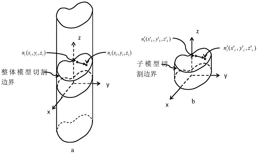
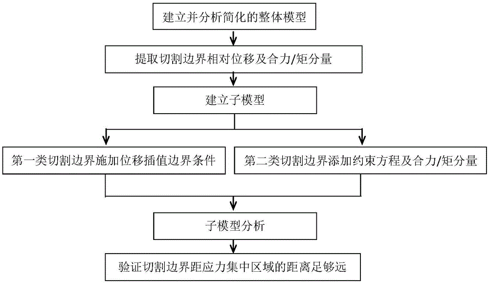
[0085] A new method for submodel finite element analysis based on cutting boundary deformation constraints, image 3 Shown is a flow chart of a new method of sub-model finite element analysis based on cutting boundary deformation coupling of the present invention; the method includes the following steps:

[0086] Step 1: Establish a simplified model of the whole machine and analyze it

[0087] Use the APDL parametric modeling language in ANSYS software to establish a simplified finite element model of the whole machine through a bottom-up modeling method;

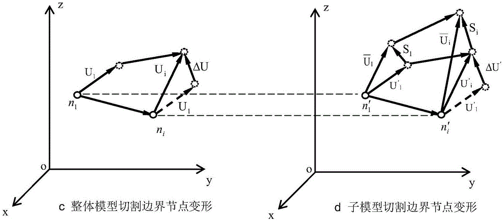
[0088] Step 2: Perform post-processing on the cutting boundary nodes of the whole machine model, and extract the resultant force component of the cutting boundary of the simplified model of the whole machine and the relative displacement of nodes. The extraction method includes the following...


PUM


Abstract

The invention discloses a new submodel finite element analysis method based on cutting boundary deformation constraint. The content of the method comprises: building a complete machine simplified model, analyzing; carrying out postprocessing to cutting boundary nodes of the complete machine model; building a finite element model-a submodel of a partial structure; adding a deformation coupling constraint equation to the cutting boundary of the submodel, adding a displacement interpolation boundary condition and a force boundary condition; analyzing the submodel; and checking that the distance from a cutting boundary to a stress gathered region is far enough. The method of the invention is advantaged by that when applying the boundary conditions to the cutting boundary of the submodel, the displacement interpolation boundary condition is added to one part of the cutting boundary, the constraint equation and the force boundary condition are added to the other part; the accuracy of the boundary conditions of the submodel is ensured; compared with the traditional submodel finite element analysis method, in adoption of the new submodel finite element analysis method, the demand of the complete machine model is reduced; the complete machine model is greatly simplified; and the complete machine analysis efficiency and the calculation precision of the submodel are improved.

Description

technical field [0001] The invention relates to a sub-model finite element analysis method, in particular to a new sub-model finite element analysis method based on cutting boundary deformation constraints. Background technique [0002] Facing the development trend of large-scale mechanical equipment today, the problem of finite element analysis of the whole machine structure of large-scale machinery is becoming more and more prominent. There are many parts and complex structures of large-scale mechanical equipment. In order to realize the analysis and calculation of the whole machine during the finite element structural analysis, it is necessary to greatly simplify the model of the whole machine on the premise of ensuring the accuracy of the overall deformation and force transmission. Ensure that the scale of the model is within the allowable range of computer capabilities. At this time, some local simplified structural stress and strain characteristics cannot be calculated...

Claims


Application Information

Patent Timeline
Patent Type & Authority Applications(China)
IPC IPC(8): G06F17/50
CPCG06F30/23
Inventor 姜文光崔哲董彬杰李润东戴玉坤
Owner JIANGSU XCMG CONSTR MASCH RES INST LTD
Why Eureka
Try Eureka