
Eureka
For R&D, Eureka makes reading and utilizing patents & technical documents easy.
Eureka AIR
Designed for self-driven R&D workflows. Generate viable solutions, solve complex R&D challenges, empower your innovation with AI.

Eureka Materials
Designed for material experts only. Revolutionize your material R&D, from search, analyze, to developing new materials.

TechResearch
Generate reliable direction feasibility study reports for your R&D in just a few steps.

TechSeek
Discover and master advanced knowledge NOW. Basics, ideas, possibilities, all at once.

TechMind
As an expert in R&D Theories, TechMind can generates customized viable solutions instantly.

TechRisk
Analyze your overall solution with one click, know your potential R&D risks in advance.

TechMonitor
Get weekly tech updates, stay abreast of the latest tech innovations and key insights.
Aqueous urea supply system for construction machine
A supply system and construction machinery technology, applied in mechanical equipment, engine components, combustion engines, etc., can solve the problems of urea water freezing, inability to cool water pipe supply pipes, etc., and achieve the effect of simple structure
- Summary
- Abstract
- Description
- Claims
- Application Information
AI Technical Summary
Problems solved by technology
Method used
Image

Examples
Embodiment Construction
[0034] One embodiment of the urea water supply system for a construction machine according to the present invention will be described below based on the drawings.
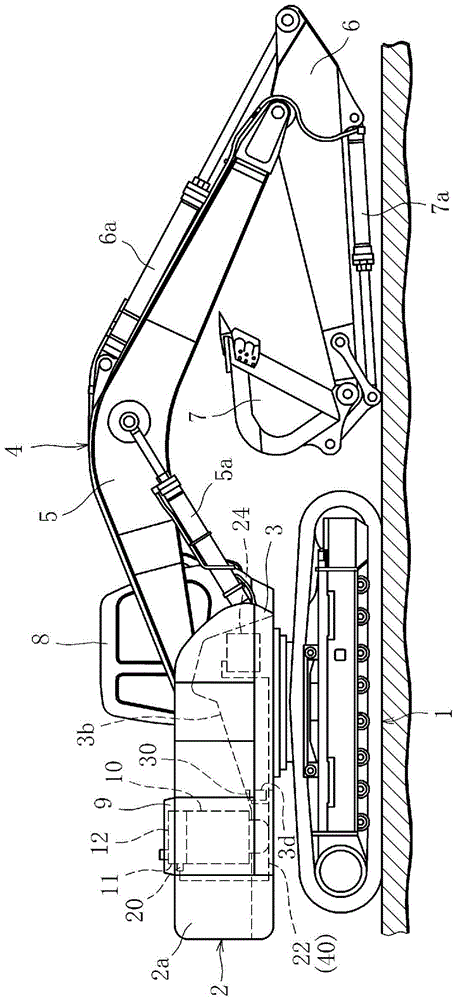
[0035] figure 1 A construction machine with the urea water supply system of the present invention is shown. In this embodiment, a crawler-type hydraulic excavator will be described as an example of a construction machine.
[0036] Such as figure 1 As shown, the hydraulic excavating mechanism has a traveling body 1, a rotating body 2 arranged on the traveling body 1 and mainly composed of a rotating frame 3, and an operation such as excavating sand and soil installed on the rotating body 2. device 4.
[0037] The working device 4 is configured to include a boom 5 rotatably attached to the swivel frame 3 in the up-down direction, an arm 6 rotatably attached to the front end of the boom 5 in the up-down direction, and an arm 6 rotatably attached in the up-down direction. A bucket 7 further mounted on the front end...
PUM
 Abstract
Description
Claims
Application Information
 - R&D Engineer
- R&D Manager
- IP Professional
- Industry Leading Data Capabilities
- Powerful AI technology
- Patent DNA Extraction
Browse by: Latest US Patents, China's latest patents, Technical Efficacy Thesaurus, Application Domain, Technology Topic, Popular Technical Reports.
© 2024 PatSnap. All rights reserved.Legal|Privacy policy|Modern Slavery Act Transparency Statement|Sitemap|About US| Contact US: help@patsnap.com