Power conversion device

A power conversion device, voltage technology, applied in the direction of high-efficiency power electronic conversion, output power conversion device, electrical components, etc., to achieve the effect of extending the period, reducing vibration and extending life

Active Publication Date: 2016-05-04
DAIKIN IND LTD
View PDF6 Cites 9 Cited by
  • Summary
  • Abstract
  • Description
  • Claims
  • Application Information

AI Technical Summary

Problems solved by technology

However, in the output of the full-wave rectification circuit, there is a power pulsation having a frequency twice the frequency of the single-phase AC voltage

Method used


Image

  • Power conversion device
  • Power conversion device
  • Power conversion device

Examples


Embodiment Construction

[0053] A. The structure of the direct type power conversion device:

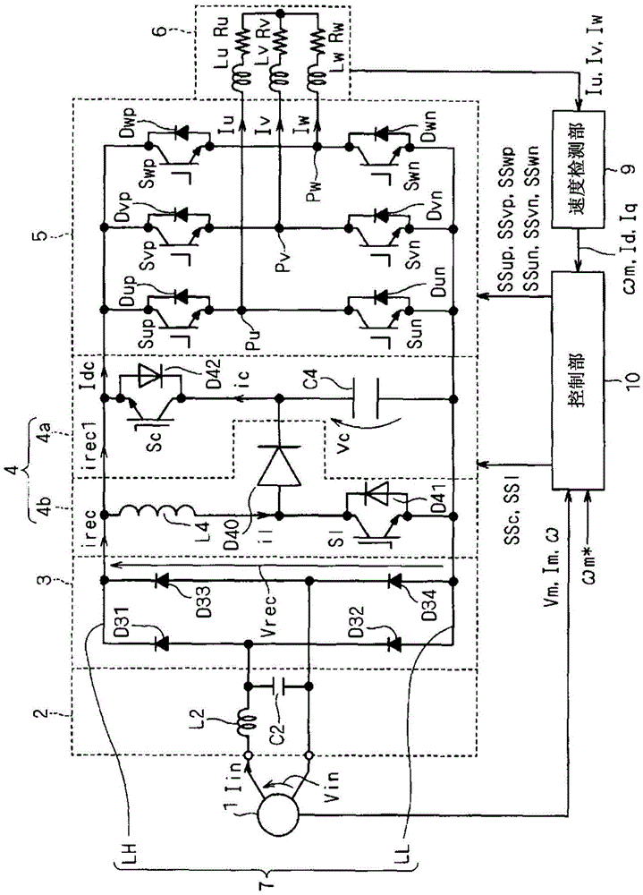
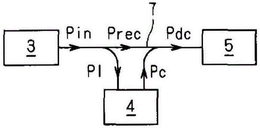
[0054] figure 1 It is a block diagram showing the configuration of a direct power conversion device to which the control method described in this embodiment is applied. This direct power conversion device has a converter 3 , a power buffer circuit 4 , an inverter 5 and a DC link 7 .

[0055] Converter 3 is connected to single-phase AC power supply 1 via filter 2, for example. The filter 2 has a reactor L2 and a capacitor C2. Reactor L2 is provided between one of the two output ends of single-phase AC power supply 1 and converter 3 . The capacitor C2 is provided between the two output terminals of the single-phase AC power supply 1 . Filter 2 removes the higher harmonic components of the current. Filter 2 can also be omitted. For the sake of simplicity, the function of filter 2 will be ignored for description below.

[0056] The DC link 7 has DC power supply lines LH, LL.

[0057] The converter 3 is, ...


PUM


Abstract

Provided is a power conversion device that reduces the power capacity that is required of a power buffer circuit. A converter (3) performs full-wave rectification with respect to a single-phase voltage (Vin) and outputs a rectified voltage (Vrec) between direct current power supply lines (LL, LH). An inverter (5) receives the rectified voltage (Vrec) and supplies three-phase alternating current (Iu, Iv, Iw) to an inductive load (6). A power buffer circuit (4) is connected between the direct current power supply lines (LL, LH). The power buffer circuit (4) comprises a discharge circuit (4a) and a charging circuit (4b). The discharge circuit (4a) comprises a capacitor (C4) and a switch (Sc) connected in series. The charging circuit (4b) is configured, for example, from a step-up chopper and comprises a switch (Sl), a reactor (L4), and a diode (D40). One part of a power pulse that is input into the converter (3) is transferred between the direct current power supply lines (LL, LH) by the power buffer circuit (4).

Description

technical field [0001] The present invention relates to a power conversion device having a power buffer circuit. Background technique [0002] In order to obtain a DC voltage from a single-phase AC voltage input from a single-phase AC power supply, a full-wave rectification circuit is generally used. However, the output of the full-wave rectification circuit has a power ripple having a frequency twice the frequency of the single-phase AC voltage. Therefore, in order to reduce the power ripple, a power buffer circuit for buffering power is required between the output side of the full-wave rectifier circuit and the load. Buffering of power requires capacitive elements such as called smoothing capacitors. [0003] Non-Patent Document 1 discloses a technique in which a smoothing capacitor is connected to a snubber capacitor via a current reversible chopper to absorb ripple power. According to this technology, by reducing the electrostatic capacitance of the smoothing capacito...

Claims


Application Information

Patent Timeline
Patent Type & Authority Applications(China)
IPC IPC(8): H02M1/15H02M5/458
CPCH02M1/15H02M3/158H02M5/458H02M1/4225H02M7/48Y02B70/10H02M1/007H02M5/4585
Inventor 榊原宪一山下尚也
Owner DAIKIN IND LTD
Why Eureka
Try Eureka