Mixed flow field flotation system driven by jet stream

A mixed flow and jet flow technology, which is applied in flotation, solid separation, etc., can solve problems such as poor working environment of fogging discs, troubles in on-site operation and maintenance work, and difficulty in timely detection, etc., to achieve efficient dispersion and mixing, and optimal boosting Work effect, the effect of reducing energy consumption cost

Active Publication Date: 2017-08-29
HEFEI JOHN FINLAY MINING EQUIP
View PDF1 Cites 0 Cited by
  • Summary
  • Abstract
  • Description
  • Claims
  • Application Information

AI Technical Summary

Problems solved by technology

As a relatively advanced coal slurry pretreatment device in the field, the flotation agent droplets are an order of magnitude smaller than the emulsified and dispersed droplets, and the dispersion effect is better; The dispersing effect of the medicine is achieved by the rotation of the fogging disc, which often requires a closed box to form a closed space to avoid the meaningless drift of the mist medicine, but the formation of the closed environment often causes problems such as fogging The working environment of the disc is poor, so it is easy to send product failures, it is impossible to realize the intuitive observation of the slurry mixing process, and it is difficult to find out the faults in time, which brings troubles to the on-site operation and maintenance work; in addition, the high-speed rotating fogging disc, The requirements for the speed of the drive motor are too high, that is, a secondary motor with a speed of up to 3000 rpm must be used to ensure its working performance, which poses severe challenges to the actual assembly, purchase and maintenance costs.

Method used


Image

  • Mixed flow field flotation system driven by jet stream
  • Mixed flow field flotation system driven by jet stream
  • Mixed flow field flotation system driven by jet stream

Examples


Embodiment Construction

[0062] For ease of understanding, combined here Figure 1-19 , the specific embodiments of the present invention are further described as follows:

[0063] Introduction of main components

[0064] The invention consists of flotation equipment and coal slurry pretreatment equipment before the flotation equipment.

[0065] 1. Flotation equipment

[0066] (1) Overall components

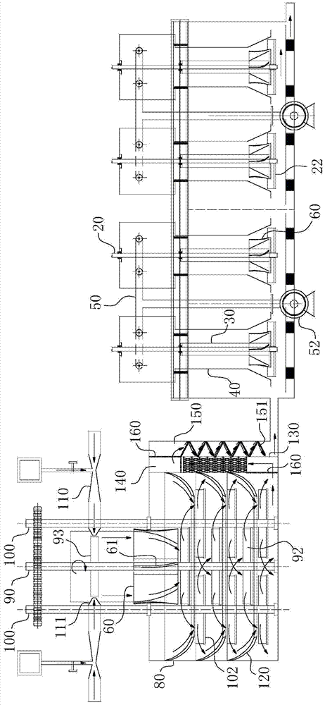
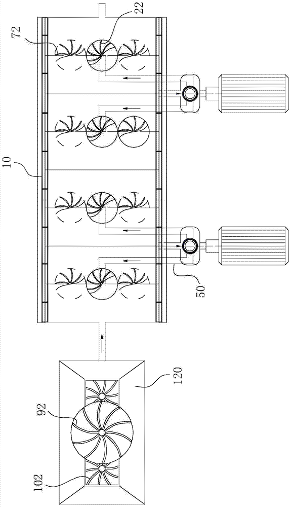
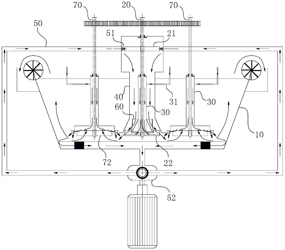
[0067] The flotation equipment is composed of a flotation cell 10, a nozzle drive mechanism, a gear mechanism, a flotation stirring assembly and a slurry circulation system. For the specific layout, as attached Figure 1-2 As shown, the entire flotation cell 10 is divided into four chambers along its cell length, and a flotation stirring assembly is arranged in each chamber. Both sides of the flotation tank 10 are provided with overflow weirs and rotating scrapers to collect flotation concentrates. One end of the flotation cell 10 connected to the coal slurry pretreatment equipment is the inlet end, ...


PUM


Abstract

The invention relates to the field of coal slurry flotation treatment, in particular to a mixed flow field flotation system based on jet flow drive. The system comprises a flotation tank and flotation stirring assemblies. Each flotation stirring assembly comprises a main shaft. An upper impeller and a lower impeller are arranged on each main shaft. Each main shaft is coaxially and sequentially sleeved with an inner sleeve and an outer sleeve outwards, and fit clearances exist between each main shaft, the corresponding inner sleeve and the corresponding outer sleeve. Suction pipes are arranged on the inner sleeves to form air channels. Coal slurry channels are formed by the fit clearances between the outer sleeves and the inner sleeves. Feeding nozzles are arranged on the upper impellers, the inlet ends of circulating feeding pipes are communicated with the flotation tank, and circulating pumps provide liquid pumping power for the circulating feeding pipes. Flow guide sleeves are coaxially fixed to the outer walls of the inner sleeves, flow guide blades are arranged in the flow guide sleeves in a circinate shape, and the rotating direction of mixed liquid guided by the flow guide blades is the same as that of the lower impellers. According to the mixed flow field flotation system, flotation energy consumption is low, the mixing effect of coal slurry and air is good, and meanwhile the flotation efficiency of existing coal slime flotation can be effectively improved.

Description

technical field [0001] The invention relates to the field of coal slurry flotation treatment, in particular to a mixed flow field flotation system driven by jet flow. Background technique [0002] Commonly used flotation machines are roughly divided into mechanical flotation machines and jet flotation machines. The disadvantage of the mechanical agitation flotation machine is that the air intake is small; the circulation of the pulp through the impeller is also small, so that its processing capacity is relatively small, and there is a stirring dead zone in the upper part of the stator. The disadvantage of the jet flotation machine is that the mixing power of the pulp and air is insufficient; the adaptability to the concentration of the pulp and the particle size is poor; there is a mixing dead zone around the central pulp feeding pipe. Since the above-mentioned flotation equipments have their own shortcomings in the working process, it is naturally difficult to achieve thei...

Claims


Application Information

Patent Timeline
Patent Type & Authority Patents(China)
IPC IPC(8): B03D1/16
CPCB03D1/16
Inventor 费之奎周伟朱金波
Owner HEFEI JOHN FINLAY MINING EQUIP
Why Eureka
Try Eureka