Linear friction-current compound heat source welding method

A welding method and composite heat source technology, applied in welding equipment, metal processing equipment, manufacturing tools, etc., can solve problems such as poor joint quality, achieve stable vibration output, good controllability, and achieve high thermal strength.

Inactive Publication Date: 2016-05-11
NORTHWESTERN POLYTECHNICAL UNIV
View PDF8 Cites 15 Cited by
  • Summary
  • Abstract
  • Description
  • Claims
  • Application Information

AI Technical Summary

Problems solved by technology

[0005] In order to overcome the shortcomings of poor joint quality when the existing linear friction welding method welds large-area workpieces, the present invention provides a linear friction-current composite heat source welding method

Method used


Image

  • Linear friction-current compound heat source welding method

Examples


Embodiment Construction

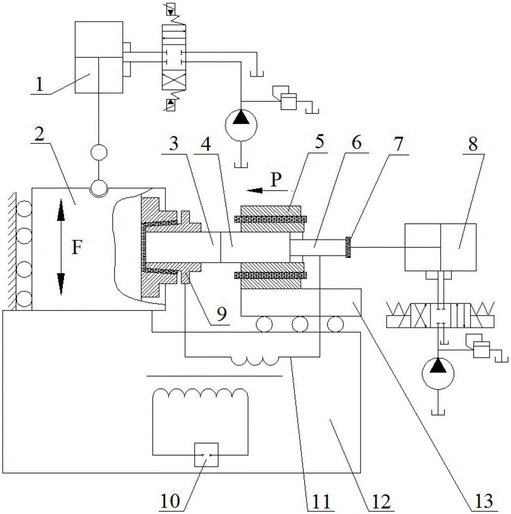
[0016] refer to figure 1 . The specific steps of the linear friction-current composite heat source welding method of the present invention are as follows:

[0017] Step 1, put the vibrating end workpiece 3 into the vibration fixture 9, set the insulating material 7 in the middle of the vibrating fixture 9 and the left end of the vibrating end workpiece 3, and cut off the current conduction between the vibrating end workpiece 3 and the bed 12 through the insulating material 7; The clamp 9 applies clamping pressure, thereby clamping the workpiece 3 at the vibrating end and insulating the workpiece 3 at the vibrating end from the bed 12;

[0018] Put the mobile end workpiece 4 into the movable fixture 5, set the insulating material 7 in the middle of the movable fixture 5 and the right end of the fixed ejector rod 6 connected with the movable end workpiece 4, and cut off the gap between the movable end workpiece 4 and the bed 12 through the insulating material 7 Current conduct...


PUM


Abstract

The invention discloses a linear friction-current compound heat source welding method for solving the technical problem of weak joint quality in welding of a large-area workpiece by a traditional linear friction welding method. Current is introduced into a friction pair when performing linear friction welding; and a welding interface is heated by using resistance heat. When a welding interface material reaches a visco-plastic state and generates deformation, that is, when a stable friction phase is reached, the current is cut off by a power supply control device; quick workpiece alignment is controlled; and higher welding upset force is applied to the workpiece to finish the workpiece welding. A compound heat source heating mode can realize the welding of high-heat-strength and large-area workpiece, relieves the load of a machine tool, is stable in vibration output of the machine tool, is excellent in controllability, can form an excellent closed welding interface in the welding process, and improves the joint quality in linear friction welding of the large-area workpiece.

Description

technical field [0001] The invention relates to a linear friction welding method, in particular to a linear friction-current compound heat source welding method. Background technique [0002] Linear friction welding uses the heat effect generated by the relative reciprocating motion friction of the contact surface of the material to be welded to realize welding. Next, relative to the surface of the fixed workpiece on the other side, the relative movement is performed with a small amplitude and an appropriate frequency. As the friction movement progresses, the friction surface is cleaned, and the friction heat makes the metal on the friction surface gradually reach a viscoplastic state and deform. Then, the two workpieces are controlled to center quickly and an upsetting force is applied to complete the welding of the workpieces. [0003] The document "Application Publication No. CN101367156A Chinese Invention Patent" discloses a linear friction welding method, which sets th...

Claims


Application Information

Patent Timeline
Patent Type & Authority Applications(China)
IPC IPC(8): B23K28/02
CPCB23K28/02
Inventor 杜随更卜昆张明王松林
Owner NORTHWESTERN POLYTECHNICAL UNIV
Why Eureka
Try Eureka