

Twist drill abrasion monitoring method
A twist drill and wear state technology, which is applied in the direction of measuring/indicating equipment, metal processing machinery parts, metal processing equipment, etc., can solve the problems of excessive size deviation, fineness, and roughness of workpieces, achieve fast running speed, improve quality and High efficiency and high recognition effect
- Summary
- Abstract
- Description
- Claims
- Application Information
AI Technical Summary
Problems solved by technology
Method used
Image

Examples
Embodiment Construction
[0029] The present invention will be further described below in conjunction with the accompanying drawings and specific embodiments.
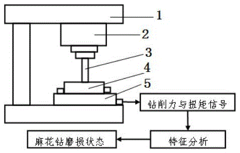
[0030] Such as figure 1 with 2 Shown, twist drill wear monitoring method of the present invention, the steps are as follows:
[0031] (1) Set the cutting parameters: set the speed of the spindle motor 2 as n; set the feed rate of the feed motor as f when the spindle motor 2 rotates one circle;
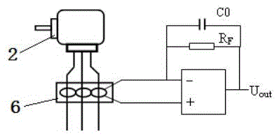
[0032] (2) When the spindle motor 2 and the feed motor work with the cutting parameters in step (1), the following four parameters of the drill bit of the twist drill 3 under normal wear, excessive wear and edge chipping are collected at a sampling frequency of 1 kHz. Three parameters: the drilling force of the twist drill 3 bit, the torque of the twist drill 3 bit, the current of the spindle motor 2 and the current of the feed motor, wherein the drilling force and torque of the twist drill 3 bit are determined by the four-component piezoelectric sens...
PUM
 Abstract
Description
Claims
Application Information