Plane joint manipulator

A technology of planar joints and manipulators, applied in the field of manipulators, can solve problems such as easy fire, oil leakage, and sensitivity to liquid temperature changes, and achieve the effects of rapid action, safe use, and fast response

Inactive Publication Date: 2016-05-11
WENZHOU POLYTECHNIC
View PDF7 Cites 3 Cited by
  • Summary
  • Abstract
  • Description
  • Claims
  • Application Information

AI Technical Summary

Problems solved by technology

[0004] The invention provides a planar joint type manipulator to solve the technical problems that the existing manipul...

Method used


Image

  • Plane joint manipulator

Examples


Embodiment Construction

[0018] In order to make the objectives, technical solutions, and advantages of the embodiments of the present invention clearer, the technical solutions in the embodiments of the present invention will be described clearly and completely in conjunction with the accompanying drawings in the embodiments of the present invention. Obviously, the described embodiments It is a part of the embodiments of the present invention, not all the embodiments. Based on the embodiments of the present invention, all other embodiments obtained by those of ordinary skill in the art without creative work shall fall within the protection scope of the present invention.

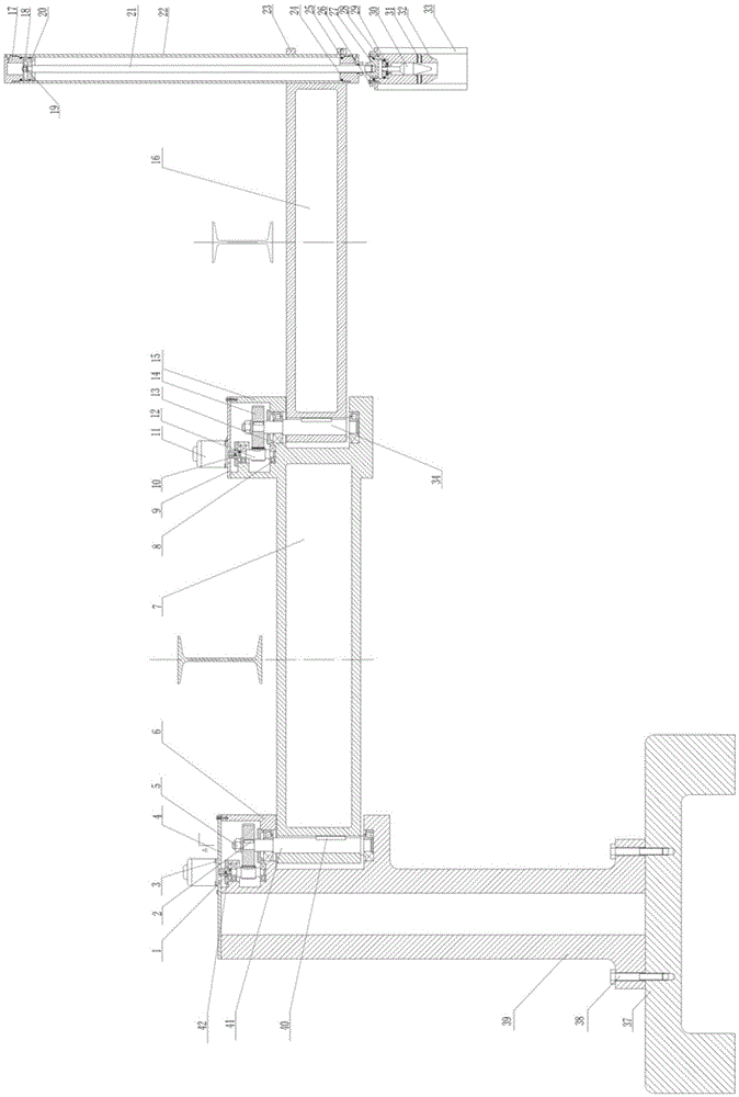
[0019] Such as figure 1 As shown, the planar articulated manipulator consists of a first key 1, a second key 2, a first screw 3, a first box cover 4, a first nut 5, a first box body 6, a boom 7, a tapered roller bearing 8, Second case cover 9, sleeve coupling 10, stepping motor 11, gear shaft 12, bearing end cover 13, gear 14, second...


PUM


Abstract

The invention discloses a plane joint manipulator. The plane joint manipulator comprises a base, a machine body, a large arm and a small arm; the machine body is fixed on the base; the large arm is arranged on the machine body through a second shaft, and can rotate with the second shaft as circle center; a joint part is arranged at the tail end of the large arm; the small arm is connected with the large arm through the joint part; and a grabbing part is arranged at the tail end of the small arm. The plane joint manipulator has the following beneficial effects: the plane joint manipulator is driven by air pressure; the air pressure is lower in working pressure, and is lower in material and precision requirements of a pneumatic component compared with hydraulic pressure; and the plane joint manipulator is free of pollution, fast in actions and response, simple in maintenance and safe in use.

Description

Technical field [0001] The invention belongs to the technical field of manipulators, and specifically relates to a plane joint manipulator. Background technique [0002] An industrial manipulator is an automated device that imitates part of the human hand's actions, and realizes grasping, transporting workpieces or operating tools in accordance with pre-set procedures, trajectories or other requirements. It has been used in production in the 1950s. It is a mechanical device developed on the basis of an automatic loading and unloading mechanism. It was mainly used to realize automatic loading and unloading and handling of workpieces, and complete single machine automation and production line automation. With the continuous expansion of the application range, it is now used to clamp tools and complete certain operations. Practice has proved that it can replace heavy manual labor, reduce labor intensity of workers, improve working conditions, and increase labor productivity. [0003...

Claims


Application Information

Patent Timeline
IPC IPC(8): B25J9/00B25J9/14
CPCB25J9/0009B25J9/14
Inventor 高斌
Owner WENZHOU POLYTECHNIC
Why Eureka
Try Eureka