Large steel structure lifting method and large steel structure lifting apparatus

A lifting device and steel structure technology, applied to cranes and other directions, can solve problems such as poor carrying capacity, danger, and difficulty in unloading, and achieve the effects of reduced section size, reasonable force, and ingenious angle design

Inactive Publication Date: 2016-05-11
上海岑晨钢结构网架有限公司
View PDF0 Cites 4 Cited by
  • Summary
  • Abstract
  • Description
  • Claims
  • Application Information

AI Technical Summary

Problems solved by technology

The gantry form cannot lift items other than the hoisting platform, for example, the gantry cannot be used to lift the lower level items on a high-rise building
[0004] The cantilever form can lift items other than the lifting platform, but due to economic constraints, it is impossible for small lifting equipment to install rotating or telescopic devices such as motors and other driving devices, so that the cantilever can only be lifted straight up and down. From a mechanical point of view, it is a bending form, and its bearing capacity is far inferior to that of the axial force form.
The tripod can lift items other than the lifting platform, and the force on the rod is in the form of axial force, but it can only be lifted straight up and down when no rotating or telescopic device is installed.
For small lifting equipment that cannot be installed with rotating or telescopic devices, if the lifting in and out positions cannot be changed, it will cause quite difficult unloading problems
[0005] The current method to deal with this problem is to hoist the items to the vicinity of the unloading platform. Since the lifting device cannot be rotated or stretched, it is necessary to use manpower to pull the items above the unloading platform before unloading
This method is dangerous and inefficient

Method used


Image

  • Large steel structure lifting method and large steel structure lifting apparatus
  • Large steel structure lifting method and large steel structure lifting apparatus
  • Large steel structure lifting method and large steel structure lifting apparatus

Examples


example 1

[0058] Example 1: as Figure 5 and Image 6 As shown, it is a non-retractable boom, including a boom 5-01, the lower end of which is hinged on the high-level floor 5-06, and a pneumatic cylinder 5-02, one end of which is hinged on the high-level floor 5-06, and the other end is hinged on the ceiling Bottom boom 5-01, the upper end of the boom 5-01 is connected to the sling 5-03 through a pulley, and the lower end of the sling is tied to the item 5-040 The ordinary boom is supported by a pneumatic cylinder, and the boom is lifted up by the pneumatic cylinder Realize the horizontal movement of goods. like Figure 5 As shown, the pneumatic cylinder is generally connected to the middle or one-third of the boom, and the distance between the connection position of the pneumatic cylinder and the support and the connection position of the boom and the support is generally one-third of the boom. ] When the cargo is 2 tons, it is known through force analysis and calculation that the ...

example 2

[0059] Example 2: as Figure 7 and Figure 8 As shown, it is another non-retractable boom, including a boom 5-01, which is fixed on the high-level floor 5-06 through two supports, and the other end extends out of the floor to form a hoisting end, and the suspending rope 5 is connected through a pulley. -03 Lift cargo 5-04. When lifting the goods for unloading, it is necessary to use manpower to pull the goods to the unloading platform 5-05.

[0060] When the weight is still 2 tons, the calculated manpower varies greatly with the length of the sling and the position of the person. The manpower is about 3kN to 8.5kN, which is equivalent to an equivalent mass of 306kg to 867kg.

example 3

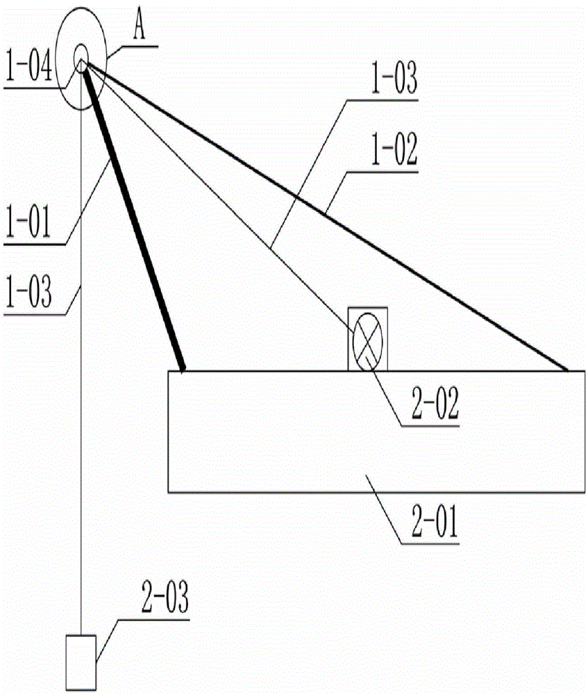
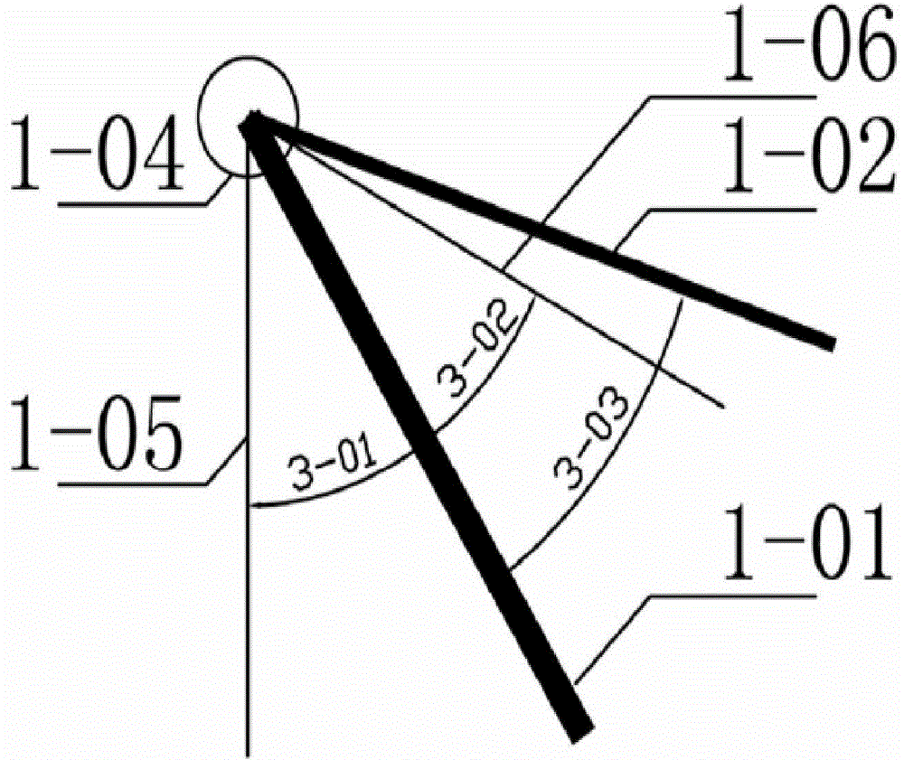
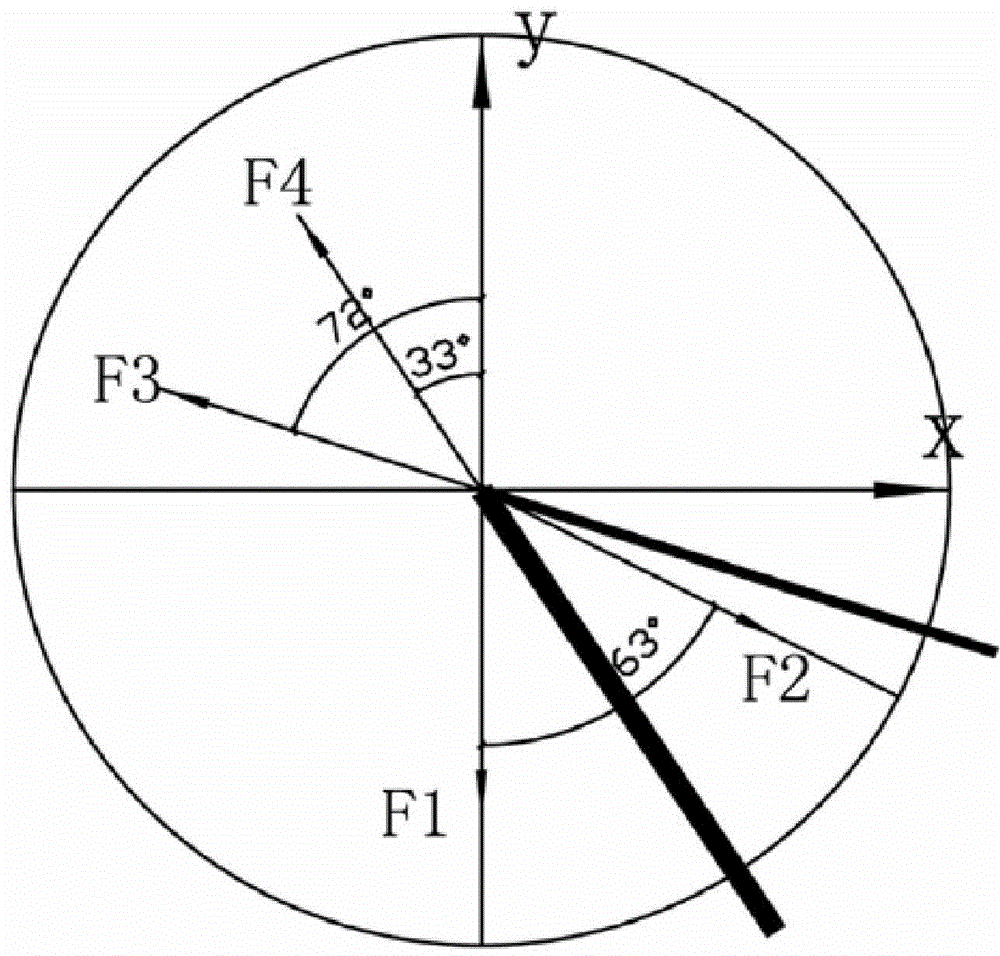
[0061] Example 3: Using the hoisting device provided by the present invention in the context of the project, using the hoisting method provided by the present invention, such as Figure 9 and Figure 10 As shown in the figure, after lifting the cargo, a vertical force is applied on the wind rope 1-02. Through any method and mechanical calculation, the axial force on the wind rope is about 1 / 40-1 / 10 compared with the gravity of the goods, while When the vertical force is applied to the wind rope, it can be calculated by mechanical method that the vertical force is about 10 / 1-1 / 5 of the axial force of the wind rope.

[0062] ] By calculation, when the weight of the cargo is 2 tons, the axial force of the wind rope is about 0.26kN, and the load applied by the person is 0.06kN, which is equivalent to 6.1kg.

[0063] It can be seen from the above three examples that the lifting weight is both 2 tons. The external force required for unloading in Example 1 is 45kN, and the equivalen...


PUM


Abstract

The present invention provides a large steel structure lifting method and a large steel structure lifting apparatus, wherein the lower end of the lifting arm in the used lifting apparatus is hinged on a platform, the upper end is hinged on end of a cable wind rope, the other end of the cable wind rope is hinged on the platform, the platform is provided with a winch, a pulley device on the upper end of the lifting rope lifting arm hangs down on the other side of the lifting arm, the outer side angle is larger than the inner side angle, the cable wind rope installation angle is larger than the inner side angle, and when the lifting height of an object exceeds the platform, the cable wind rope is artificially pulled so as to place the object on the platform. The present invention further provides the lifting apparatus used in the lifting method. According to the lifting method and the lifting apparatus of the present invention, the reasonable force rod member, ie., lifting arm is used, and the special lifting method is used, such that the lifting inlet-outlet position adjusting can be achieved when the special rotation and stretching deice is not installed.

Description

technical field [0001] The invention relates to the technical field of building hoisting, provides a hoisting method, and also provides a hoisting device used in the hoisting method. Background technique [0002] With the development of the construction industry, the field of hoisting has also developed rapidly. The most common lifting method in the prior art is to use a cantilever structure, which can be rotated and adjusted with a motor; another common lifting method is to use a gantry structure. For lifting large objects, moving in a larger space, [0003] The hoisting method and hoisting device of the gantry structure are relatively simple and practical; in actual projects, due to the construction speed, terrain or space constraints, when the aforementioned large hoisting devices of the cantilever structure and gantry structure are inefficient or difficult to use, it is necessary to use suitable The most commonly used small lifting devices are gantry, cantilever and tr...

Claims


Application Information

Patent Timeline
Patent Type & Authority Applications(China)
IPC IPC(8): B66C23/20
Inventor 廉嘉美
Owner 上海岑晨钢结构网架有限公司
Why Eureka
Try Eureka