Hydraulic system for combined machine tool

A technology of hydraulic system and combined machine tool, which is applied in the direction of fluid pressure actuation system components, mechanical equipment, servo motor components, etc., to achieve the effects of high temperature measurement sensitivity, reduction of hydraulic cylinder impact, and strong applicability

Inactive Publication Date: 2016-05-11
NANTONG INST OF TECH
View PDF8 Cites 1 Cited by
  • Summary
  • Abstract
  • Description
  • Claims
  • Application Information

AI Technical Summary

Problems solved by technology

The hydraulic system only includes the clamping function and is not suitable for the combined machine tool for multi-function teaching

Method used


Image

  • Hydraulic system for combined machine tool
  • Hydraulic system for combined machine tool
  • Hydraulic system for combined machine tool

Examples


Embodiment Construction

[0032] The present invention will be described in further detail below in conjunction with the accompanying drawings and embodiments. It should be understood that the specific embodiments described here are only used to explain the present invention, not to limit the present invention.

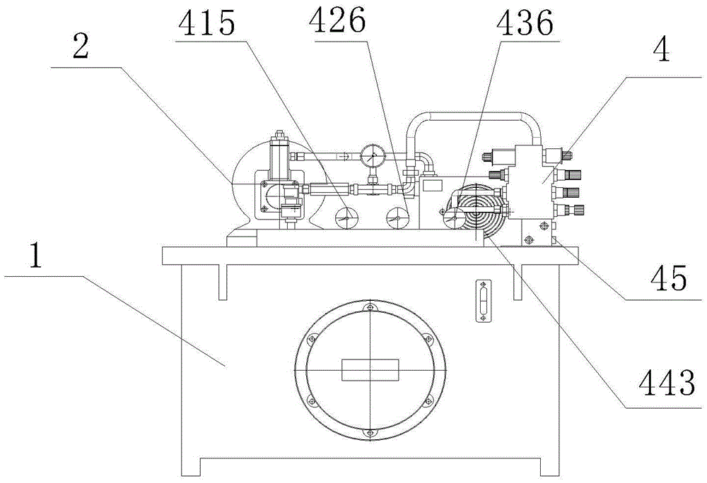
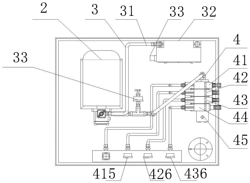
[0033] Such as figure 1 , figure 2 , image 3 , Figure 4 , Figure 5 , Image 6 , Figure 7 , Figure 8 with Figure 9 , this specific embodiment discloses a hydraulic system for a combined machine tool, including a base 1, a hydraulic pump assembly 2, an oil pressure circuit 3 and an electromagnetic stack valve assembly 4, and the hydraulic pump assembly 2, the oil pressure circuit 3 and an electromagnetic stack valve The component 4 is located on the base 1 and is fixedly connected thereto through screws and nuts.

[0034] Specifically, refer to figure 1 , figure 2 with image 3 , the base 1 includes a base shell 11 and an oil tank 12, the oil tank 12 is located inside the bas...


PUM


Abstract

The invention provides a hydraulic system for a combined machine tool. The hydraulic system comprises a base, a hydraulic pump assembly, an oil hydraulic circuit and an electromagnetic sandwich valve assembly; the hydraulic pump assembly, the oil hydraulic circuit and the electromagnetic sandwich valve assembly are located on the base and are fixedly connected with the base; the electromagnetic sandwich valve assembly comprises a tail frame sandwich valve set, a milling head box locking sandwich valve set, a grinding head box locking sandwich valve set, a chuck sandwich valve set and a multi-connected bottom plate block; and the tail frame sandwich valve set, the milling head box locking sandwich valve set, the grinding head box locking sandwich valve set and the chuck sandwich valve set are located at the upper end of the multi-connected bottom plate block and are fixedly connected with the multi-connected bottom plate block. The hydraulic system is compact in structure and has the beneficial effects of being flexible in configuration, integrated and general.

Description

technical field [0001] The invention relates to the technical field of mechanical machine tool hydraulic system structural design, in particular to a hydraulic system for combined machine tools. Background technique [0002] Combined machine tools are semi-automatic or automatic special-purpose machine tools based on general-purpose components, equipped with special components and fixtures designed according to the specific shape and processing technology of the workpiece. CNC machine tools mainly process linear cylinders, oblique cylinders, arcs and various threads, grooves, worms and other workpieces. At present, most of the CNC teaching still stays on the machine tool with a single processing method, and it is impossible to compare different mechanical processing methods and principles, and it is impossible to carry out combined processing. Different processing methods (including turning, milling, drilling, grinding, threading, etc.) require different types of machine to...

Claims


Application Information

Patent Timeline
Patent Type & Authority Applications(China)
IPC IPC(8): F15B13/06F15B21/04F15B11/16
CPCF15B13/06F15B11/16F15B21/042F15B2013/002
Inventor 顾海孙健华吴宣东顾拥军张捷李朱锋李彬王贵成
Owner NANTONG INST OF TECH
Why Eureka
Try Eureka