
A method for testing non-steady thermal conductivity and the testing device used

A technology of thermal conductivity and testing device, applied in the direction of thermal conductivity of materials, etc., can solve the problem of inability to accurately measure the non-constant thermal conductivity of materials, and achieve the effect of filling the gap in the industry

Active Publication Date: 2018-09-11
CHINA THREE GORGES UNIV
View PDF5 Cites 0 Cited by
  • Summary
  • Abstract
  • Description
  • Claims
  • Application Information

AI Technical Summary

Problems solved by technology

[0004] The technical problem to be solved by the present invention is to provide a non-steady-state thermal conductivity test method and the testing device used, which can solve the problem that the traditional constant-state test method cannot accurately measure the non-steady-state thermal conductivity of the material without destroying the sample. Under the premise of the non-steady heat conduction process, the temperature data of specific points inside the material are obtained, and then the thermal conductivity of the material is obtained by using the least square finite element back calculation method through the temperature data of these points, and the test results are accurate.

Method used


Image

  • A method for testing non-steady thermal conductivity and the testing device used
  • A method for testing non-steady thermal conductivity and the testing device used
  • A method for testing non-steady thermal conductivity and the testing device used

Examples


Embodiment 1

[0064] A method for non-steady-state thermal conductivity test, the method comprises the following steps:

[0065] 1) Apply temperature disturbance to the sample to obtain non-steady-state heat conduction temperature data inside the material;

[0066] 2) Through the temperature data, the least square method is used to perform multivariate function fitting on the non-steady thermal conductivity;

[0067] 3) Based on the least square finite element method, according to the temperature value of each node, the non-steady state process of the thermal conductivity of the material is inversely calculated, and the non-steady state thermal conductivity is obtained.

[0068] The sample and multiple sensors are symmetrically arranged, apply temperature disturbance to the sample, and circulate heating within a certain temperature range to allow the temperature to spread evenly to the sample, and then collect temperature data at different radii at different times to obtain non-steady-state...

Embodiment 2

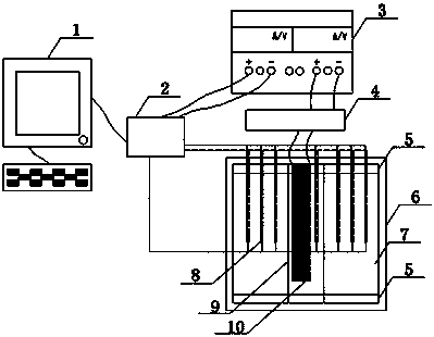
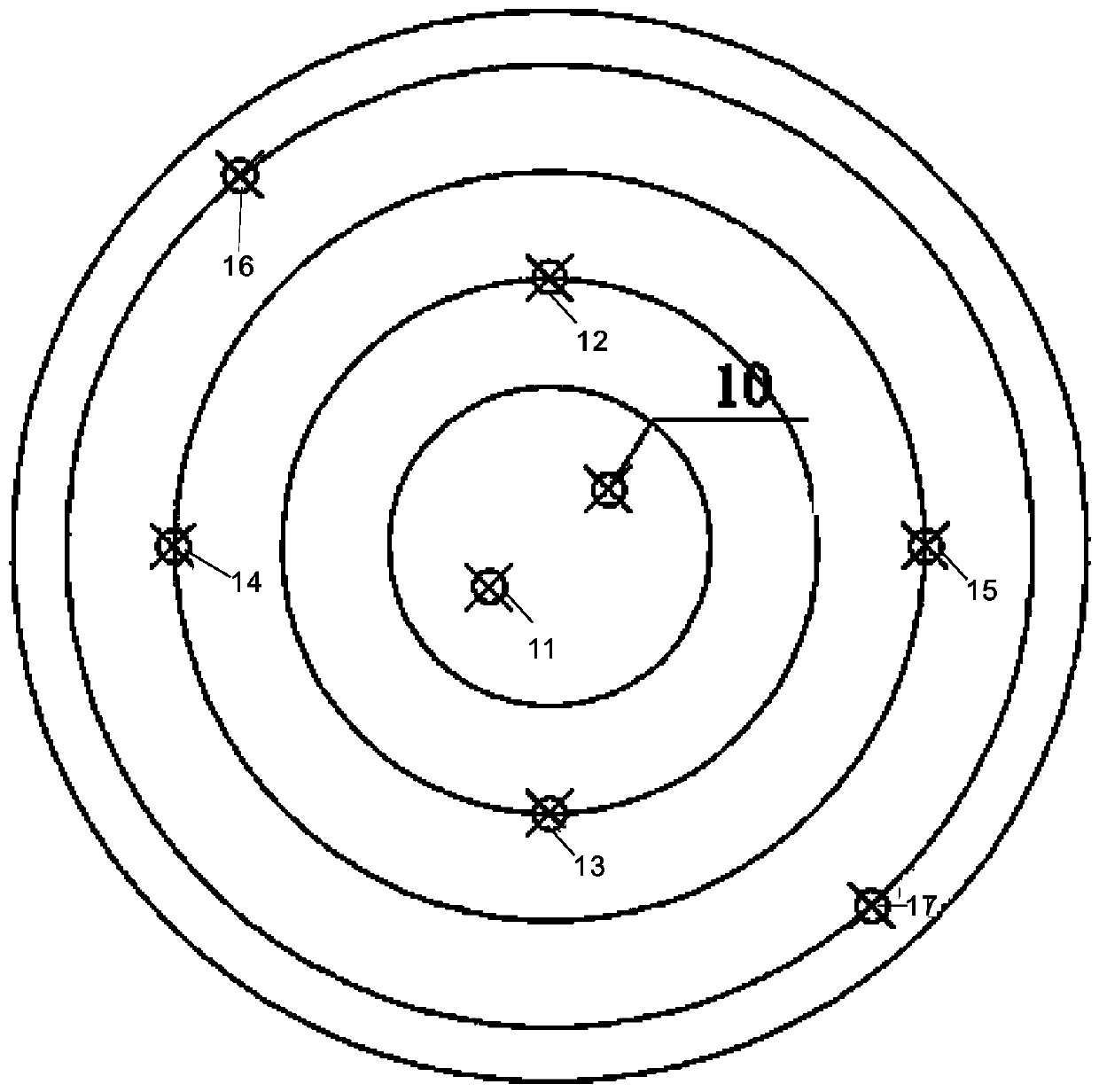
[0094] Such as figure 1 with figure 2 As shown, a test device for collecting sample temperature data in testing non-steady thermal conductivity by the above method,

[0095] It includes mold testing device, temperature control system and data acquisition system;

[0096] In the test mold device, a circular foam board 5 is arranged at the bottom of the test mold 6, and a steel pipe 9 is inserted in the center of the test mold 6;

[0097] In the temperature control system, the single-ended heating rod 10 connected to the relay 4 is arranged in the center of the steel pipe 9, and the relay 4 is connected to the power supply 3;

[0098] The data acquisition system includes a plurality of temperature sensor groups 8. Among the plurality of temperature sensor groups 8, the first temperature sensor 11 is arranged inside the steel pipe 9, and the second temperature sensor 12 and the third temperature sensor 13 are arranged symmetrically. The temperature sensor group composed of fo...

Embodiment 3

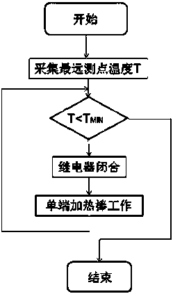
[0109] Such as image 3 As shown, a method for automatically applying the temperature disturbance to the sample by using the above-mentioned test device, the method is:

[0110] The initial state of the relay 4 is disconnected when the test is set to start, and the temperature collection module 2 collects the temperature of the sixth temperature sensor 16 or the seventh temperature sensor 17 farthest away from the center of the sample 7 as T, when TWhen the highest temperature is set, the relay 4 is disconnected, the channel of the single-ended heating rod 10 and the power supply 3 is cut off, and the heating is stopped, which is used as a heating cycle to realize the automatic application of temperature disturbance to the sample and perform multiple heating Cycling constitutes a non-steady heat conduction process.

[0111] In order to control the time of one cycle and improve the discrimination of the temperature value of each temperature measuring point, the minimum temperat...


PUM


Abstract

A non-steady state thermal conductivity coefficient testing method comprises the following steps: (1) applying temperature disturbance on a sample and obtaining the non-steady state thermal conductivity temperature data in the material; (2) through the temperature data, carrying out multivariate function fitting on non-steady state thermal conductivity coefficient by a least square method; (3) based on a least square finite element method, back-calculating the non-steady state process of thermal conductivity coefficient of the material according to the temperature values of each node so as to obtain the non-steady state thermal conductivity coefficient. The provided method and device can solve the problem that the conventional steady state measuring method can not accurately measure the non-steady state thermal conductivity coefficient, and are capable of obtaining the temperature data of specific points in a material during the non-steady state thermal conductivity process without destroying the sample. Through the temperature data of the points, the thermal conductivity coefficient of the material can be obtained through a least square finite element back calculation method, and the results are accurate.

Description

technical field [0001] The invention relates to the measurement of the non-steady-state thermal conductivity of multi-phase porous media in the field of engineering thermodynamics, in particular to a method for testing the non-steady-state thermal conductivity and a testing device used therefor. Background technique [0002] The transfer of heat from a place with a higher temperature to a lower place is a common thermodynamic heat conduction phenomenon, and the thermal conductivity of a substance can usually be characterized by the thermal conductivity. Thermal conductivity refers to the heat transfer through an area of ​​1 square meter in 1 second for a material with a thickness of 1m and a temperature difference of 1 degree between the two sides of the material under stable heat transfer conditions. The unit is W / m·degree (W / (m·K)), used to represent the strength of thermal conductivity under the unit gradient. It is widely used in mass concrete temperature control, temp...

Claims


Application Information

Patent Timeline
Patent Type & Authority Patents(China)
IPC IPC(8): G01N25/18
CPCG01N25/18
Inventor 郝霜童富果霍少君薛松
Owner CHINA THREE GORGES UNIV
Learn More