
Power line fault location device and method

A technology of fault distance measurement and power line, which is applied to the fault location and uses the pulse reflection method to detect faults and other directions. It can solve the problems of poor DC pulse destructive power, increased fault point resistance, and unsatisfactory problems, and achieves a large fault point penetration capability. , to achieve the effect of integration and rapid ranging

Inactive Publication Date: 2016-05-11
CHINA PETROLEUM & CHEM CORP +1
View PDF11 Cites 15 Cited by
  • Summary
  • Abstract
  • Description
  • Claims
  • Application Information

AI Technical Summary

Problems solved by technology

There are several problems in this method: 1. The DC pulse has a cumulative effect on the solid insulation of the undamaged part of the cable, which affects the life of the cable. The existing test procedures have clearly stipulated that the DC withstand voltage test of the cable is not performed; 2. The destructive power of the DC pulse is relatively poor. , and may even lead to an increase in the resistance of the fault point, and in severe cases, it cannot be broken down; 3. The discharge gap or switch needs to break the DC current, and the failure rate is high
However, the oscillating wave high voltage superimposed by the equipment has a high DC component, and there is also a DC cumulative effect of cable insulation, which does not meet the requirements of the current test regulations; at the same time, the AC and DC superimposed withstand voltage and AC withstand voltage are equivalent no mature verification

Method used


Image

  • Power line fault location device and method
  • Power line fault location device and method
  • Power line fault location device and method

Examples


Embodiment 1

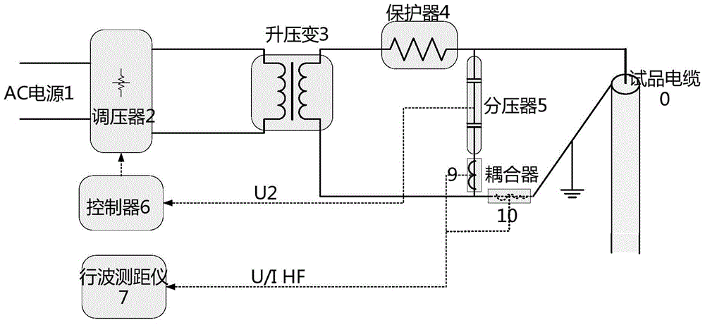
[0063] If you choose to process high-frequency AC voltage to the test product, you need to apply AC high voltage to the test product through a power frequency AC high-voltage device. figure 2 The structure and test wiring diagram of the power line fault location method are shown. refer to figure 2 , The system of the present invention includes an AC power supply 1 , a voltage regulator 2 , a step-up transformer 3 , a protector 4 , a voltage divider 5 , a controller 6 , a traveling wave range finder 7 , a voltage coupler 9 or a current coupler 10 . Wherein, the input end of the voltage regulator 2 is connected to the AC power source 1 , after voltage regulation, a part of the input voltage is taken as the output voltage, and the output voltage is input to the step-up transformer 3 . The step-up transformer 3 boosts the voltage of the input voltage, one end of the secondary side winding of the step-up transformer 3 is grounded, the other end is connected to the test object 0 ...

Embodiment 2

[0067] If you choose to process high-frequency AC voltage to the test product, you need to apply AC high voltage to the test product through a power frequency AC high-voltage device. Since the AC power needs to be boosted to the AC voltage, it will cause relatively large power loss. Therefore, the present invention improves Embodiment 1 by adopting power frequency series resonance technology. For the sake of simplicity, the following only focuses on two embodiments The differences are described in detail.

[0068] Such as Figure 5 As shown, a power frequency AC high voltage device is provided in this embodiment. The device includes: a voltage regulator 2, an excitation transformer 3, an adjustable inductance 11, a voltage divider 5, a controller 6, a traveling wave rangefinder 7, a coupling The input end of the voltage regulator 2 is connected to the AC power source 1, and the output voltage is input to the excitation transformer 3 after voltage regulation; one end of the se...

Embodiment 3

[0071] If you choose to add frequency conversion series resonant high voltage to the test product, you need to add AC high voltage to the test product through the frequency conversion series resonant high voltage device. Since the AC power needs to be boosted to the AC voltage, it will cause a relatively large power loss. Therefore, the present invention improves Embodiment 1 by adopting frequency conversion series resonance technology. For the sake of simplicity, the following only focuses on the two embodiments. The differences are described in detail.

[0072] Such as Figure 8 As shown, a frequency conversion series resonant high-voltage device is provided in this embodiment, and the device includes: a frequency converter 2, an excitation transformer 3, an inductor 4, a voltage divider 6, a controller 7, a traveling wave range finder 7, and a coupler; The input end of the frequency converter 2 is connected to the industrial frequency power supply 1, the output end is conn...


PUM


Abstract

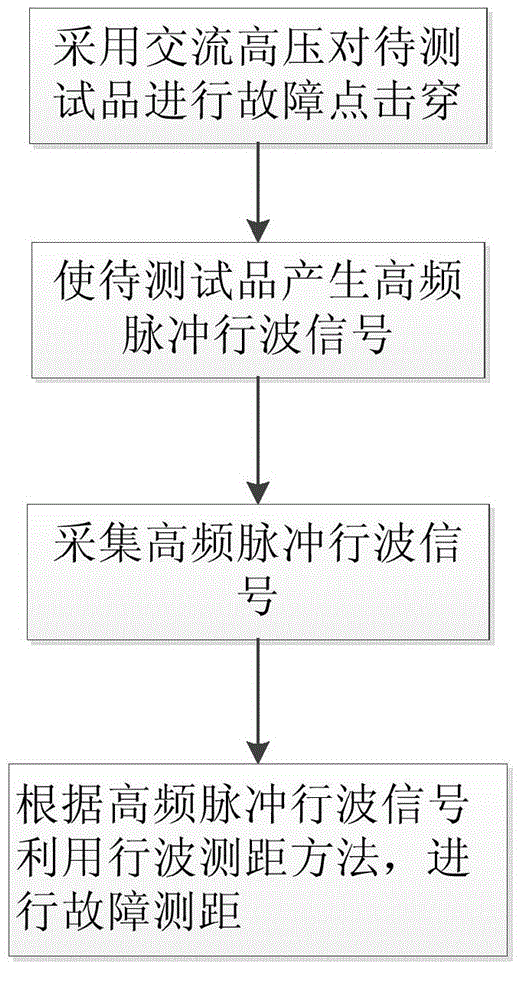
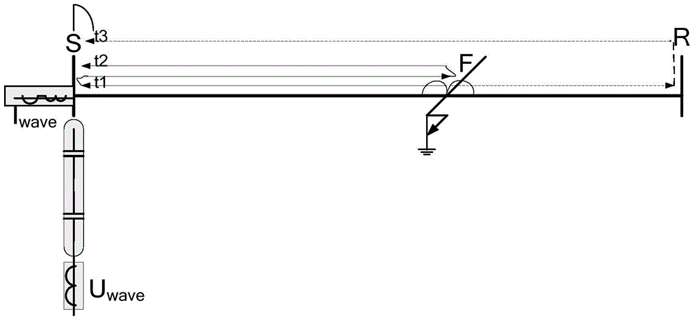
The invention discloses a power line fault location device and method. The method of the invention includes the following steps that: alternating-current high voltage is adopted to perform breakdown on a cable fault point; time difference of the arrival of fault traveling wave signals at line terminals is measured; and a distance from the fault point to the line terminal is calculated . The system is composed of an alternating-current high voltage generator, a traveling wave range finder and a corresponding measurement and control part. According to the power line fault location device and method of the invention, a variety of kinds of alternating-current high voltage generators can be adopted, such as a power-frequency alternating-current test device, a power-frequency resonance test device, a variable frequency resonance test device and an ultra-low frequency alternating-current test device; requirements of current test procedures can be satisfied; a cumulative effect on insulation caused by fault point direct current pulses or oscillation breakdown can be avoided; alternating-current high voltage is adopted to realize fault point breakdown for power lines such as a cable, and therefore, breakdown strength is high, and a breakdown effect is better; automatic ranging of a fault which occurs in a power line alternating current withstand voltage test can be realized, and alternating current withstand voltage testing and fault location can be completed simultaneously.

Description

technical field [0001] The invention relates to a power line fault ranging device and a ranging method, belonging to the technical field of power equipment testing. Background technique [0002] Power lines are the channels for transmitting electric energy and are the main components of the power grid. High-voltage overhead lines are usually used. In some areas with tight land use or high requirements for line lightning protection and explosion protection, more power cables are used. Generator and transformer lead-out lines often use enclosed busbars and tubular busbars, and some use overhead lines or power cables. [0003] The faults of power lines in the power system account for more than 80% of the total faults. Overhead lines are located in the wild and are easily affected by weather such as lightning strikes and strong winds. Most of them are instantaneous faults. It takes time and labor to find fault points. Try sending electricity shock to solve. Usually, the distan...

Claims


Application Information

Patent Timeline
Patent Type & Authority Applications(China)
IPC IPC(8): G01R31/11
Inventor 时振堂李志远王乐钱志红杜红勇秦文杰
Owner CHINA PETROLEUM & CHEM CORP
Learn More