
Self-adaptive two-dimensional finite element sparse and dense grid interface transition method

A finite element, self-adaptive technology, applied in special data processing applications, instruments, electrical digital data processing, etc., can solve the problems of inconvenient calculation, singular stiffness matrix, and no published invention patents.

Inactive Publication Date: 2016-05-11
NANJING UNIV OF AERONAUTICS & ASTRONAUTICS
View PDF5 Cites 0 Cited by
  • Summary
  • Abstract
  • Description
  • Claims
  • Application Information

AI Technical Summary

Problems solved by technology

The basic idea of ​​these methods is to adjust the stiffness term in the conventional finite element equations, reflect the additional energy generated by the displacement inconsistency in the stiffness, and then perform the overall solution to solve the uncoordinated transition between grids, but because these methods need to spend It takes a lot of time and energy to select the number of virtual nodes on the interface, and the number of virtual nodes selected by different methods is different. When the number of virtual nodes is not selected properly, the stiffness matrix is ​​singular
In addition, the accuracy of the calculation result is limited by the interpolation function at the virtual node, which brings great inconvenience to the calculation
At present, there is no more efficient finite element grid transition method at home and abroad, and there is no published invention patent

Method used


Image

  • Self-adaptive two-dimensional finite element sparse and dense grid interface transition method
  • Self-adaptive two-dimensional finite element sparse and dense grid interface transition method
  • Self-adaptive two-dimensional finite element sparse and dense grid interface transition method

Examples


Embodiment

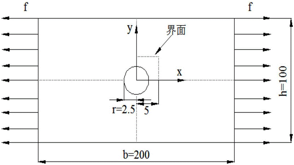
[0106] as attached figure 2 The two ends of the slab with the geometric dimensions shown are subjected to a uniform tensile load f, and the length and width of the slab are respectively:

[0107] b=200, h=100, the radius of the hole r=2.5; the distance from the interface to the center of the circle is 5.

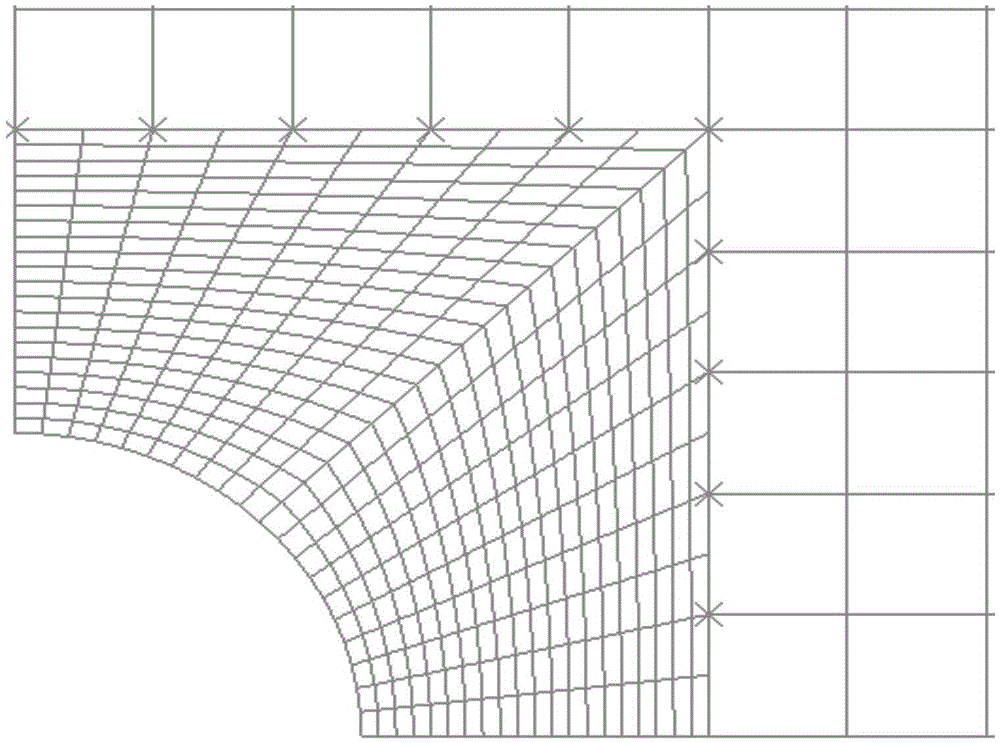
[0108] Using symmetry, only 1 / 4 of the plate is modeled; a finer mesh is used between the holes and the interface, and a sparser mesh is used for other parts. A conventional finite element model including nodes was established using finite element software (see the attached image 3 ) and models using the interface transition method without nodes (see attached Figure 4 ) for comparative analysis. The plane stress four-node quadrilateral element CSP4 is used for meshing. Each part of the interface applies 5 interface units.

[0109] The calculation results of the two methods are basically the same. Horizontal displacement U across the interface 1 (see attached Figu...


PUM


Abstract

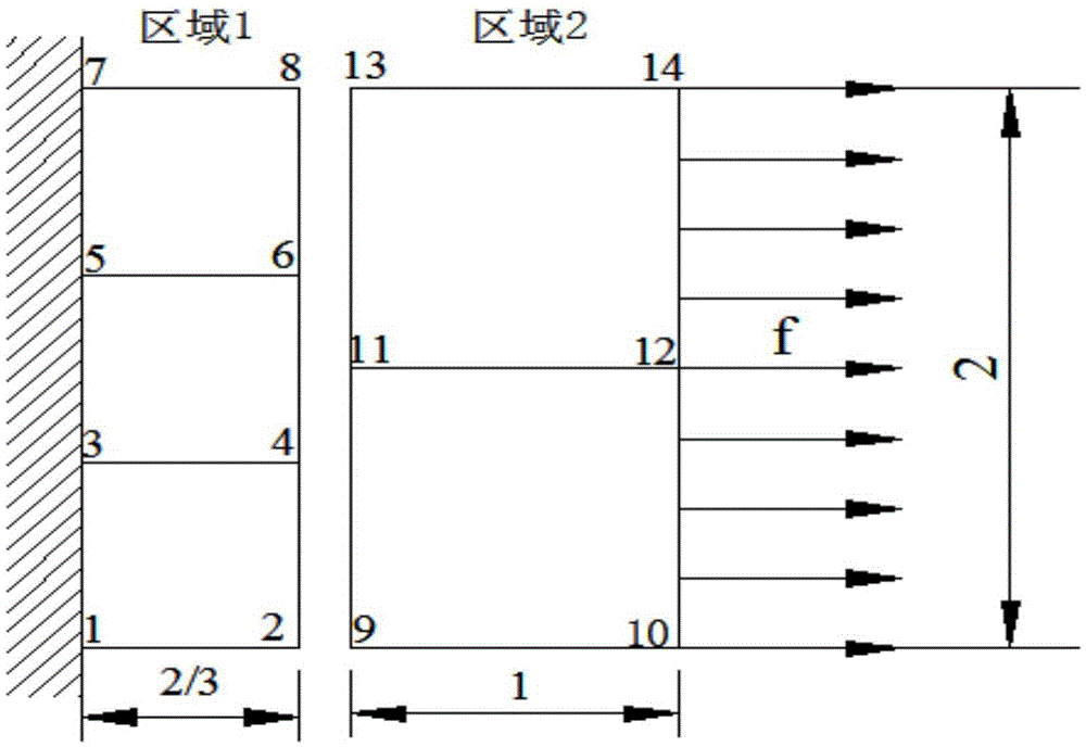
The invention discloses a self-adaptive two-dimensional finite element sparse and dense grid interface transition method which is applied to the field of engineering structure analysis. The method comprises the following steps: forcing displacement of finite element nodes in different sparse and dense grid sub-regions to be continuous through penalty factors in a least square manner, so as to obtain an interface transition element and system rigidity matrix according to the principle of minimum potential energy; introducing the rigidity matrix into commercial finite element software through a user unit subprogram interface; selecting the proper penalty factor only by setting the material attribute, the geometrical feature, the load and other properties of the unit by the user so as to realize the two-dimensional finite element grid interface transition. The method can effectively solve the local refinement problem when the finite element grids are divided and the remote docking problem of finite element models established in different regions, by different analysts and by adopting different types of finite element software, has self-adaptability, and is simple and practicable, high in computational accuracy, small in occupied internal storage and high in computation speed.

Description

technical field [0001] The invention relates to the field of engineering structure analysis, in particular to an adaptive two-dimensional finite element density grid interface transition method. Background technique [0002] As an approximate numerical solution for discretizing continuous elastic bodies, the finite element method can obtain approximate solutions because it can simulate structures with complex geometric shapes and calculate the field problems of complex structures; at the same time, because the problem-solving steps have been systematic and Standardization, with a considerable number of flexible and general-purpose computer programs, can solve various engineering problems, and has become one of the most widely used and most effective numerical calculation methods in engineering calculations. [0003] The basic idea of ​​discrete elements in classical finite element grids is to transmit displacement and force through mutually coordinated nodes. It is required ...

Claims


Application Information

Patent Timeline
Patent Type & Authority Applications(China)
IPC IPC(8): G06F17/50
CPCG06F30/23
Inventor 孙志刚
Owner NANJING UNIV OF AERONAUTICS & ASTRONAUTICS
Learn More